
Beverage Dispensing Unit with Openable Pinch Valve

a technology of beer dispensing unit and pinch valve, which is applied in the direction of liquid dispensing, liquid flow controller, packaging, etc., can solve the problems of increasing the cost of system use, generating too much waste, and too expensive beer bottled or canned, and achieves the effect of convenient disassembly and replacement of tapping units

Active Publication Date: 2015-05-14
ANHEUSER BUSCH INBEV SA
View PDF3 Cites 6 Cited by
  • Summary
  • Abstract
  • Description
  • Claims
  • Application Information

AI Technical Summary

Benefits of technology

The patent unit describes a device that is used for dispensing liquids. The device includes a column that has a part that can be opened to separate the first and second jaws, making it easier to insert a new dispensing tube and engage it with the jaws. Additionally, the device can be used as a standalone device with wheels for easy movement. The technical benefits of the patent device are improved ease of use and mobility.

Problems solved by technology

Furthermore, above a critical volume of consumption, serving bottled or canned beer would be too expensive and would generate too much waste.
It is clear that providing a shut-off valve to a disposable tube increases substantially the cost of use of the system.
Furthermore, it can be quite cumbersome to drive up a flexible dispensing line through the hollow column which outlet to the cooling chamber is positioned at the back thereof and can easily be appreciated when looking e.g., at FIG. 2 of US2004 / 0226967.
In spite of the various solutions proposed to simplify it, the “bottom-up” installation of a disposable dispensing tube remains cumbersome since the user must crouch and engage the head and shoulders into the cooling chamber to access the opening connecting the cooling chamber to the dispensing column inner channel, push up the flexible tube either all the way up to the dispensing head like in US2004 / 0226967, or only until the outlet of the tube reaches the opening in the column as in WO2009 / 115928 and in EP1982952, at which point it must be grabbed from the outside before it falls back all the way down into the cooling chamber.
Since this operation must be repeated with each new keg installed into the cooling chamber, if the installation of the tube is too uncomfortable, users may become reluctant to use such roving beverage dispensing unit.
The change of dispensing tube with every new keg remains a rather delicate operation, often to be performed in the dark, in noisy and crowded environment, and also in stressful conditions.

Method used


Image

  • Beverage Dispensing Unit with Openable Pinch Valve
  • Beverage Dispensing Unit with Openable Pinch Valve
  • Beverage Dispensing Unit with Openable Pinch Valve

Examples


Embodiment Construction

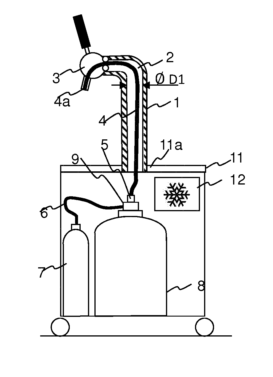
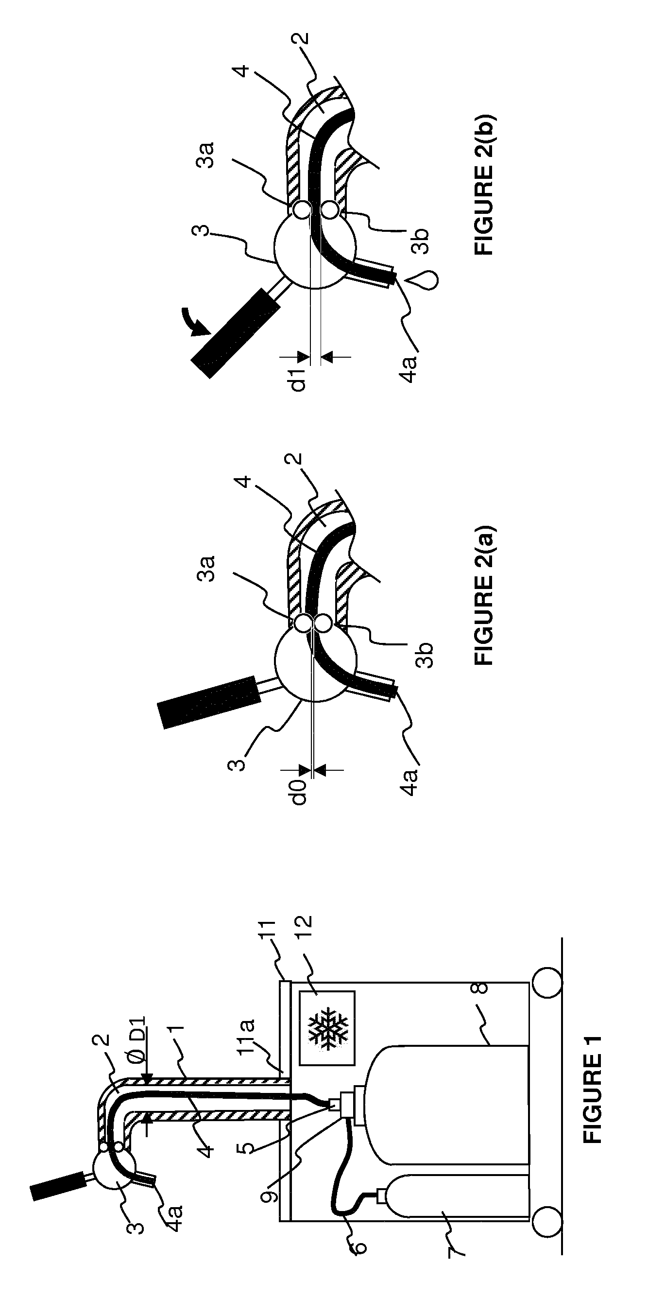
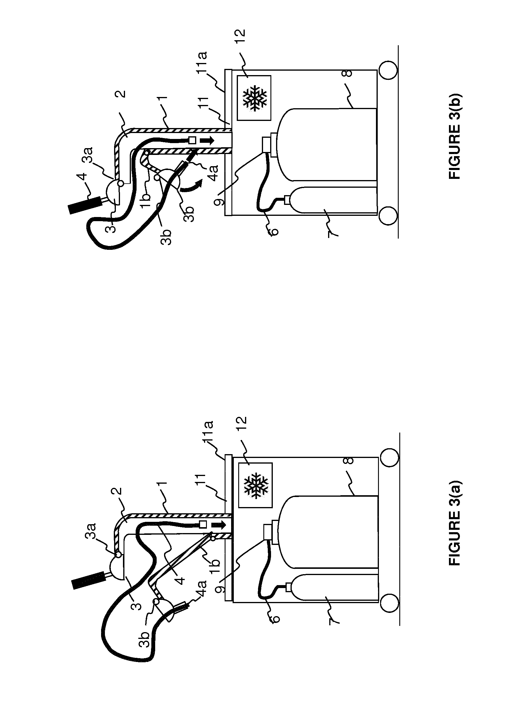
[0035]As illustrated in FIG. 1, the present invention concerns a beverage dispensing unit for dispensing a beverage from a pressurized container (8). The dispensing unit illustrated in FIG. 1 is a roving unit, provided with wheels to facilitate the displacement thereof, e.g., for use at temporary events. The present invention, however, is not restricted to roving dispensing units, and applies to any dispensing unit comprising tapping column (1), comprising an elongated portion extending substantially normal to the top surface (11a) of a support plate (11) provided with an opening and forming at the top thereof an elbow. One end—the “bottom end”—of said tapping column is fixed to the top surface (11a) and the column comprises an elongated inner channel (2) bringing in fluid communication the opening of the support plate with a tapping pinchvalve (3a, 3b) located in a tapping head (3) positioned at or adjacent the elbow at the opposite top end of the tapping column and opening to ambi...


PUM


Abstract

A dispensing unit for dispensing a beverage from a pressurized container having a tapping column fixed to and extending normal to the top surface of a top plate with an opening and forming an elbow is disclosed. The column has an elongated inner channel bringing in fluid communication the support plate with a tapping pinch valve located in a tapping head at the elbow. The tapping pinch valve has jaws for receiving in pinching relationship the outlet end of the dispensing line and controlling flow of liquid by varying the distance between the jaws from a closed to an open position. A flexible dispensing line, having inlet and outlet ends, extends in the channel. The outlet end engages the pinch valve, and the inlet end connects to a keg. A device for opening the channel includes the pinch valve so a distance larger than the open position separates the jaws.

Description

TECHNICAL FIELD OF THE INVENTION[0001]The present invention concerns beverage dispensing units for dispensing a beverage, typically a carbonated beverage like beer, from a pressurized container through a dispensing tube and a dispensing tap. In particular, it concerns a beverage dispensing unit allowing a highly simplified loading and unloading of a dispensing line.BACKGROUND OF THE INVENTION[0002]Draught beer is often preferred by consumers to bottled or canned beer. Draught beer is generally served at the counter of a public house out of a refrigerated keg provided with a fluid connection to a source of pressurized gas for driving the dispensing of the beer through a dispensing line fluidly connecting the keg to a dispensing tap, comprising a valve for controlling the flow out of said tap. In case of a temporary social event outside a public house, such as an outdoor event, wedding party, fair and the like, consumers like to be offered draught beer for consumption. Furthermore, ab...

Claims


Application Information

Patent Timeline
Patent Type & Authority Applications(United States)
IPC IPC(8): B67D1/14B67D1/08B67D1/00
CPCB67D1/1405B67D1/0004B67D2001/0094B67D2001/0098B67D1/0857B67D1/06B67D2210/00041B67D1/0412B67D1/1252B67D1/1477B67D2001/0092B67D2001/0093
Inventor PEIRSMAN, DANIELVAN HOVE, SARAHVAN ROMPAEY, JOHAN
Owner ANHEUSER BUSCH INBEV SA
Learn More