
Dual clutch transmission

a dual clutch transmission and gearwheel technology, applied in the direction of belt/chain/gearing, toothed gearing, toothed gearing, etc., can solve the problems of premature damage of the bearing, large axial force, and no relative rotation, and the operation conditions of a small bearing are very unfavorable for small bearings

Active Publication Date: 2015-05-14
VOLVO LASTVAGNAR AB
View PDF16 Cites 4 Cited by
  • Summary
  • Abstract
  • Description
  • Claims
  • Application Information

AI Technical Summary

Benefits of technology

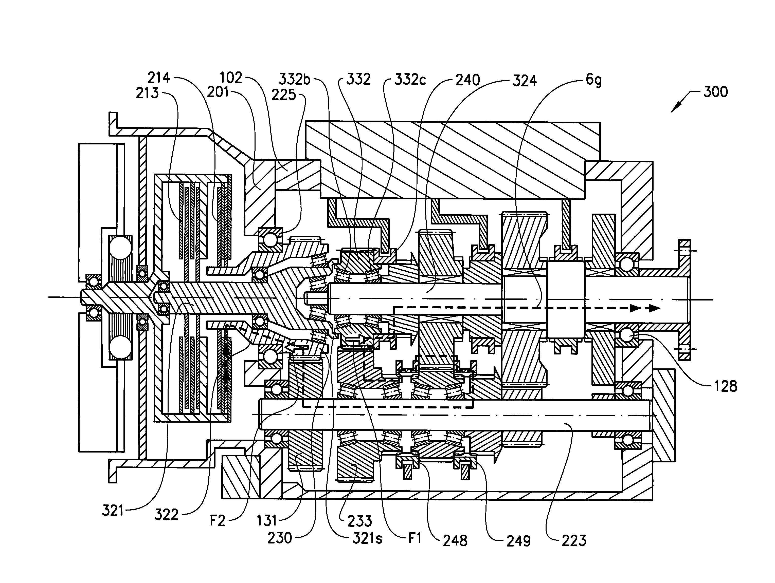
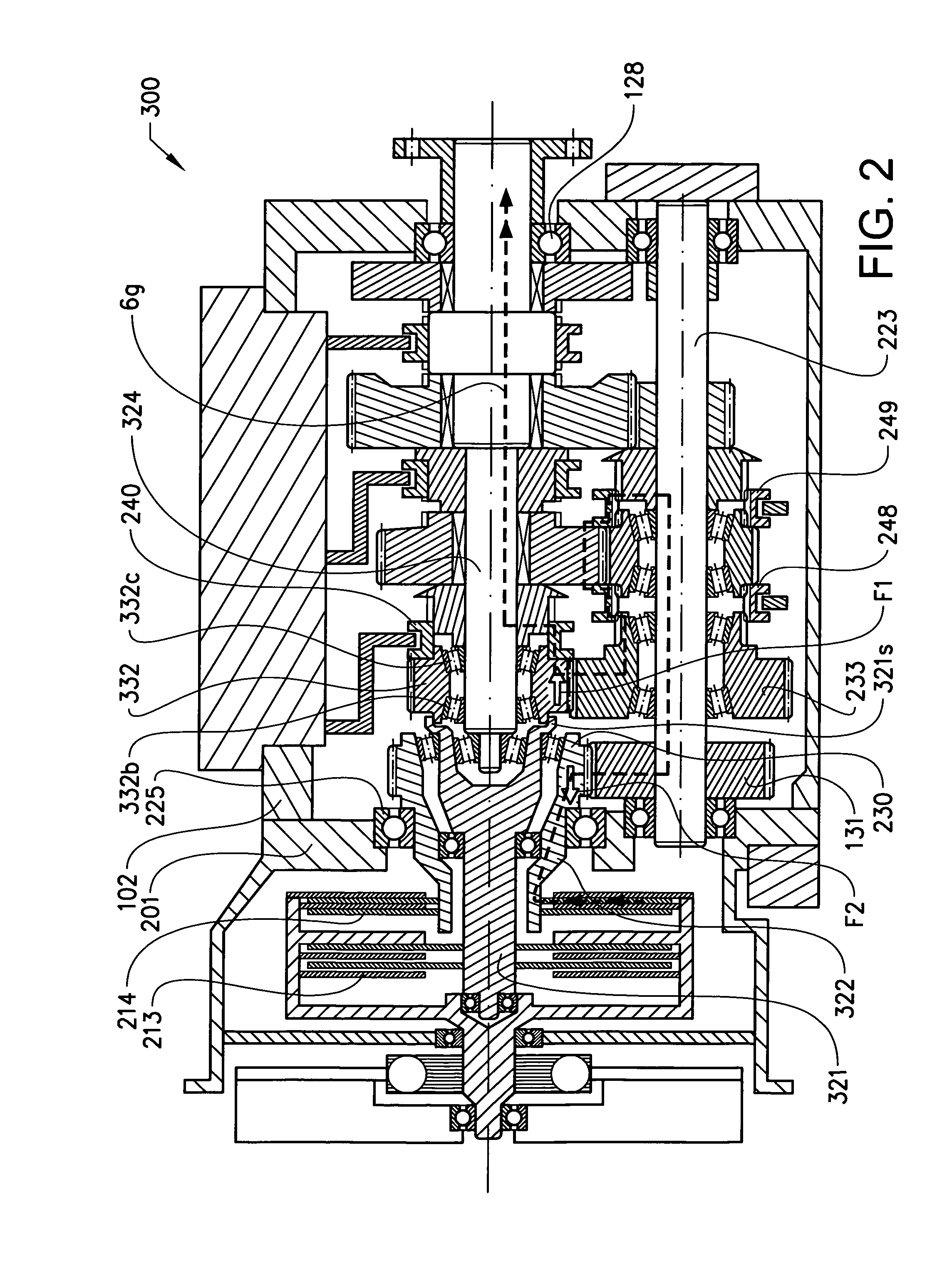
The invention provides a gear arrangement in a dual-clutch transmission that reduces the load on the pilot bearing when there is no relative rotation. The first input shaft is designed to withstand high axial loads and the first input gearwheel is mounted on conical roller bearings that can be moved axially between a distanced and a contact position. This allows for the transfer of axial forces to the first input shaft and reduces the load on the pilot bearing. The first input gearwheel is mounted on a first and a second roller bearing that allows for axial displacement. A radially inwards directed protrusion on the first input gearwheel allows for this axial displacement.

Problems solved by technology

These large axial forces are a problem especially in gear speeds when there will be no relative rotation in the main pilot bearing.
Large axial forces and no relative rotation are very unfavourable operating conditions for a small bearing.
Fretting wear may occur, which will lead to premature damage of the bearing.
There is however no room available for a larger bearing.

Method used


Image

  • Dual clutch transmission
  • Dual clutch transmission
  • Dual clutch transmission

Examples


Embodiment Construction

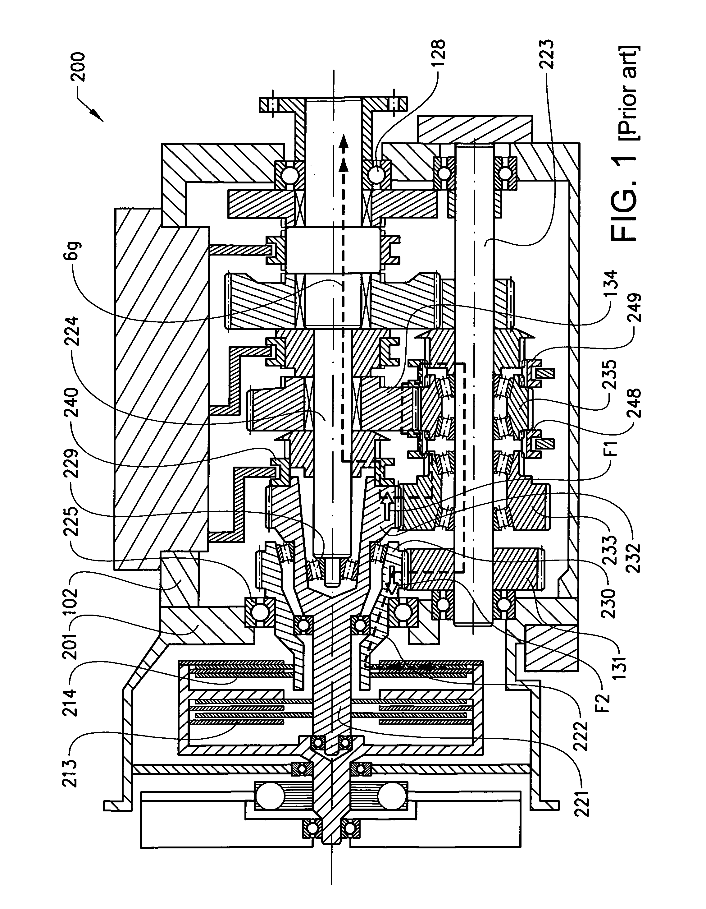
[0021]FIG. 1 shows a prior art dual clutch transmission 200, when it is in engine drive. The dual clutch transmission 200 is arranged inside the main housing 102, there are a first input shaft 221 and a second input shaft 222. The first input shaft 221 can be rotationally driver by the first clutch disc set 213, and the second input shaft 222 can be rotationally driven by the second clutch disc set 214.

[0022]According to the prior aft first primary gear teeth 232 are rotationally fixed to or integral with the first input shaft 221 and second primary gear teeth 230 are rotationally fixed to or integral with the second input shaft 222. A centre shaft 224 is coaxial with the input shafts 221 and 222 and a countershaft 223 is parallel thereto. The second input shaft 222 is suspended in the clutch housing 201 by an input shaft bearing 225. Between the centre shaft 224 and the first input shaft 221 a main pilot bearing 229 is arranged. An adequate suspension of the centre and input shafts...


PUM


Abstract

A dual clutch transmission includes a first and a second input shaft provided with a first and second input arrangement, respectively, a centre shaft, a countershaft, and a first and a second primary gear step. The first and second input shaft are coaxially arranged with the centre shaft and can transfer torque from the first and second input means to the countershaft via the first and the second primary gear step. The first primary gear step including a first input gearwheel and a first driven gearwheel. The first input gearwheel is rotationally fixed with the first input shaft. The first input gearwheel is arranged upon the centre shaft.

Description

BACKGROUND AND SUMMARY[0001]The present invention relates to the arrangement of gearwheels in a dual clutch transmission, especially a dual clutch transmission for on-road vehicles.[0002]In a dual clutch transmission with coaxial input and output shafts, a small main pilot bearing is arranged between the centre shaft and the first input shaft. The pilot bearing is subjected to large axial forces in some gear speeds. The large axial forces originate from the helical gears, which when transferring torque are subjected to a gear mesh force. These large axial forces are a problem especially in gear speeds when there will be no relative rotation in the main pilot bearing. Large axial forces and no relative rotation are very unfavourable operating conditions for a small bearing. Fretting wear may occur, which will lead to premature damage of the bearing.[0003]U.S. Pat. No. 5,181,431 discloses example of prior art.[0004]A solution o the problem would be to increase the size of the bearing....

Claims


Application Information

Patent Timeline
Patent Type & Authority Applications(United States)
IPC IPC(8): F16H3/091F16H3/00
CPCF16H3/006F16H3/0915F16H57/023F16H2003/0807Y10T74/19228F16H3/091
Inventor HEDMAN, ANDERS
Owner VOLVO LASTVAGNAR AB
Learn More