
Brace and tension springs for a brace

a technology of tension springs and braces, applied in the field of braces, can solve the problems of affecting the mobility and/or affecting the ability to support the injured person, and conventional springs that do not provide sufficient force to significantly enhance the extension of the kn

Active Publication Date: 2015-04-30
SPRING LOADED TECH
View PDF3 Cites 25 Cited by
  • Summary
  • Abstract
  • Description
  • Claims
  • Application Information

AI Technical Summary

Benefits of technology

The patent is about a new type of brace for supporting and extending the extension of a limb, specifically a knee brace. The brace uses a hydraulic compression spring, which is a light-weight, consistent force curve, and effective in providing support and resisting buckling of the knee. The technical effect of this new brace is to provide better support and extension of the knee, assisting in the recovery and prevention of knee injuries. The hydraulic compression spring used in the brace is a new type of spring that has not been previously used in knee braces.

Problems solved by technology

Many individuals suffer from knee problems, often due to a prior knee injury.
Some such problems can significantly affect mobility and / or the ability to support the injured person.
However, conventional springs do not provide sufficient force to significantly enhance knee extension or resist buckling of the knee.
Additionally, a brace for a limb can be designed to provide a specific force profile or ‘force curve’ over the range of motion of the user's limb, and it is important to maintain a consistent force curve over the thousands of cycles that such a brace is likely to be used, which can be difficult to achieve using conventional springs.
However, a significantly longer stroke is required for applications such as knee braces, and this is problematic given the forces Forcing the piston into the spring can be equivalent to applying up to a 1500 lb. end load on a 0.125″ steel rod that is more than an inch long.
The piston will buckle unless it is very carefully guided, which can damage or destroy the piston, the seal, or both.

Method used


Image

  • Brace and tension springs for a brace
  • Brace and tension springs for a brace
  • Brace and tension springs for a brace

Examples


Embodiment Construction

[0037]The invention will be described in the context of a knee brace 2 for humans. However, it will be appreciated that the principles of the invention apply equally to braces for other human body appendages and to braces for animals including (without limitation) horses, dogs and cats It will also be appreciated that a tension spring of the invention can advantageously be used in many other applications and the principles of the invention will apply equally. It will further be appreciated that all the advantages of the invention do not necessarily apply to every embodiment.

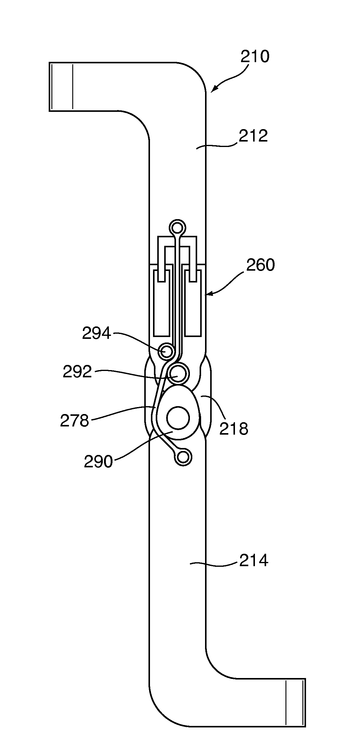
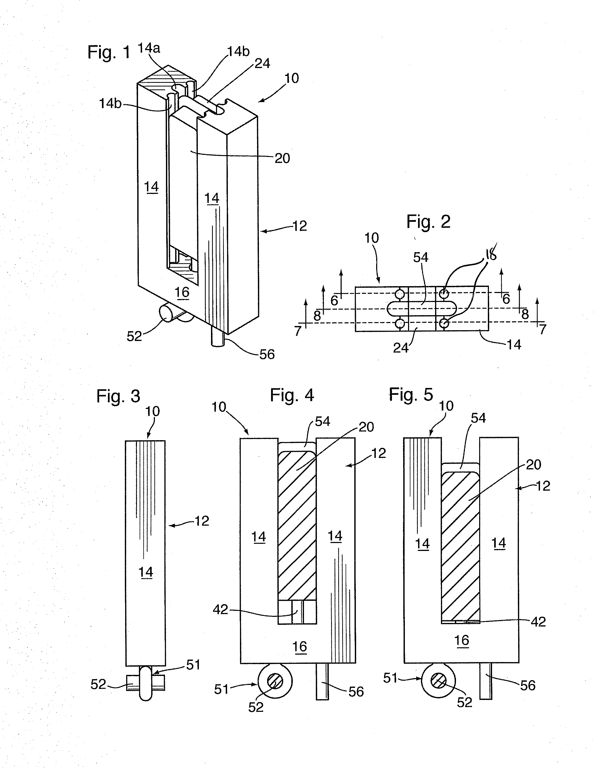
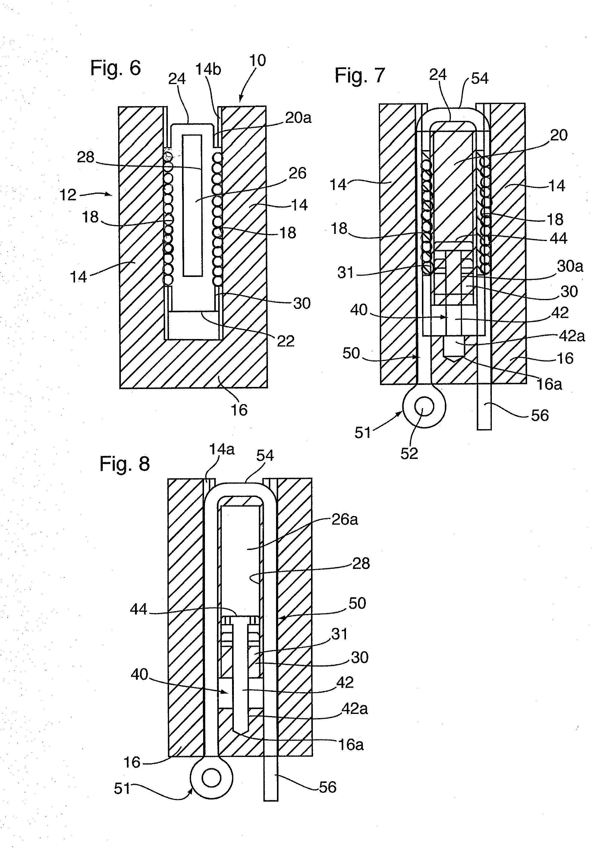
[0038]An embodiment of a compression element comprising a hydraulic tension spring 10 according to the invention is illustrated in FIGS. 1-5. The spring 10 comprises a block 12 comprising opposed guide legs 14 maintained in fixed spaced apart relation by a base 16. Opposed interior faces of the legs 14 each provide a cord guideway 14a for receiving a cord 50, as described below, and in the preferred embodiment co...


PUM


Abstract

A brace for augmenting extension of a user's limb about a joint comprises an upper arm pivotably attached to a lower arm. At least one compression element is attached to at least one of the upper and lower arms, and a substantially inelastic tensioning element is affixed to the other of the upper and lower arms over at least one tensioning member. Applying a force to bend the brace to a flexed position loads the compression element, and upon removal of the flexing force the compression element applies a restoring force to urge the brace back to the extended position. The compression element may comprise a hydraulic tension spring comprising at least one cylinder having a sealed portion defining a liquid containment space, and a piston comprising a compressing portion having a smaller diameter than the cylinder and extending axially through a hydraulic seal into the liquid containment space. A guide for maintaining the piston oriented axially relative to the frame maintains piston alignment so that when the frame is fixed in place and tension is applied to the tensioning member, the compressing portion of the piston rod intrudes further into the liquid containment space, compressing the hydraulic fluid and loading the spring.

Description

CONTINUATION DATA[0001]This application is a continuation-in-part of U.S. application Ser. No. 14 / 317,447 filed Jun. 27, 2014, which is incorporated by reference herein in its entirety. This application also claims benefit of Canadian Application No. 2,831,507 filed Oct. 31, 2013.FIELD OF INVENTION[0002]This invention relates to braces, and in particular a brace for supporting and / or assisting the extension of a limb, and springs used with such braces.BACKGROUND OF THE INVENTION[0003]As is well known, a knee brace can perform a purely prophylactic function, or provide an assistive force that helps the user to extend their knee, or both. Knee braces can provide physical protection against injury, and may for example be used by athletes involved in high-risk sports where there is a relatively high susceptibility to sustaining a knee injury.[0004]Many individuals suffer from knee problems, often due to a prior knee injury. Some such problems can significantly affect mobility and / or the...

Claims


Application Information

Patent Timeline
IPC IPC(8): A61F5/01
CPCA61F5/0123A61F2005/0134A61F2005/0179A61F5/0125A61F5/013A61F2005/0169A61F2005/0197
Inventor GARRISH, ROBERT
Owner SPRING LOADED TECH
Learn More