Hall electromotive force compensation device and hall electromotive force compensation method
a technology of electromotive force compensation and compensation device, which is applied in the field of hall electromotive force compensation device and hall electromotive force compensation method, can solve the problems of varying the magnetic sensitivity of the semiconductor integrated circuit of the magnetic sensor
- Summary
- Abstract
- Description
- Claims
- Application Information
AI Technical Summary
Benefits of technology
Problems solved by technology
Method used
Image

Examples
first embodiment
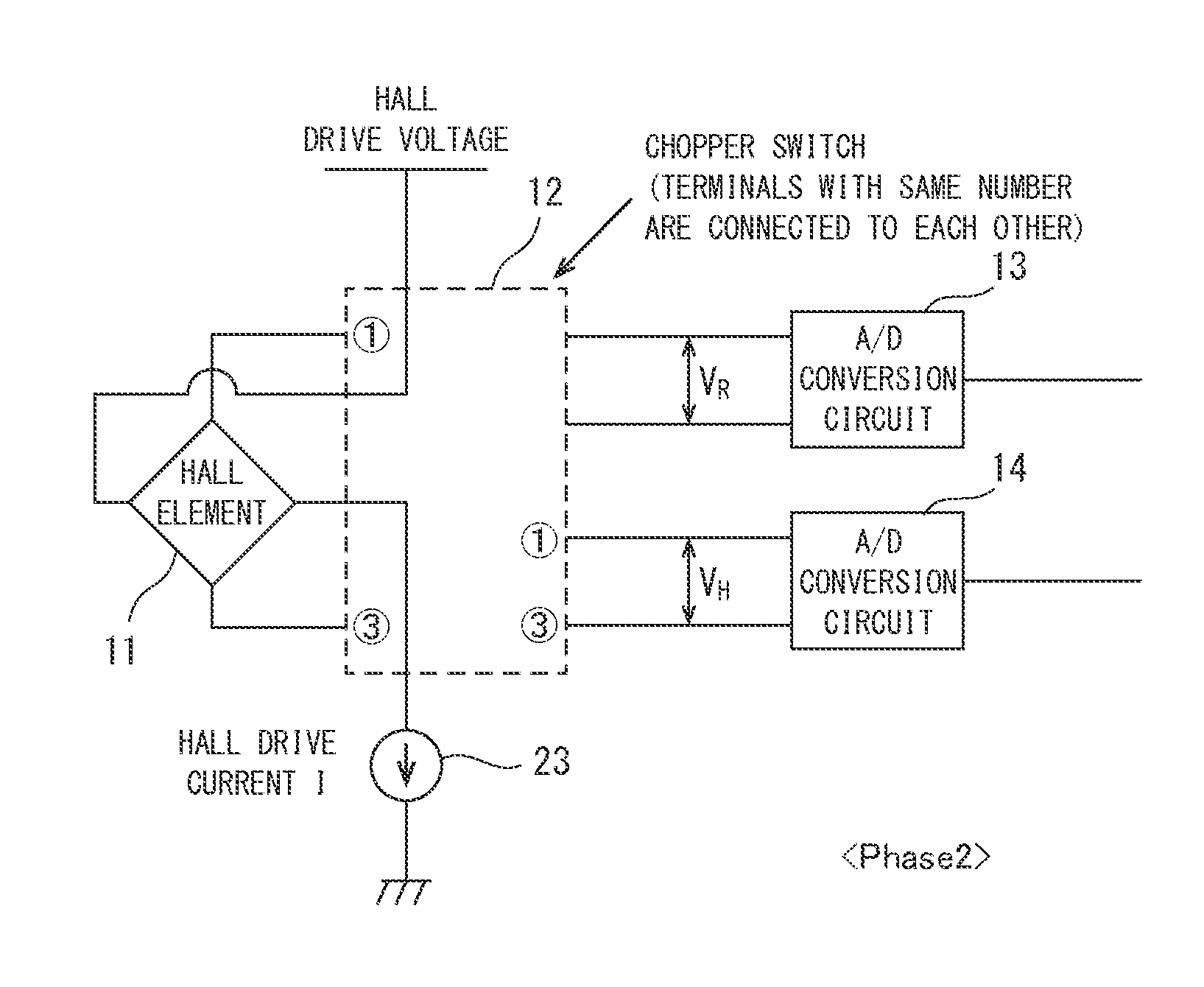
[0110]FIG. 6 is a configuration block diagram illustrating a Hall electromotive force compensation device according to the first embodiment of the present invention. In the drawings, reference numeral 11 represents a Hall element, reference numeral 12 represents a chopper switch, reference numeral 13 represents a Hall resistance measurement unit (A / D conversion circuit), reference numeral 14 represents a Hall electromotive force measurement unit (A / D conversion circuit), reference numeral 15 represents a temperature sensor (temperature measurement unit), reference numeral 16 represents an A / D conversion circuit, reference numeral 19 represents a Hall electromotive force compensation unit, reference numeral 20 represents a compensation signal generation unit, reference numeral 21 represents a compensation coefficient calculation circuit, reference numeral 22 represents a Hall electromotive force compensation circuit, reference numeral 23 represents a Hall drive current source, refere...
second embodiment
[0145]FIG. 12 is a configuration block diagram illustrating the Hall electromotive force compensation device according to the second embodiment of the present invention. In the drawings, reference numeral 31 represents a shared A / D conversion circuit. It is noted that the same numerals are assigned to the components having the same functions as those in FIG. 6. Further, the descriptions of the Hall resistance measurement unit 13 and the Hall electromotive force measurement unit 14 are omitted.
[0146]The Hall electromotive force compensation device in the second embodiment includes the shared A / D conversion circuit 31, which is commonly used by the Hall resistance measurement unit 13, the Hall electromotive force measurement unit 14, and the temperature measurement unit 15. That is, the resistance value from the Hall resistance measurement unit 13, the Hall electromotive force from the Hall electromotive force measurement unit 14, and the temperature value from the temperature measure...
third embodiment
[0148]FIG. 13 is a configuration block diagram illustrating the Hall electromotive force compensation device according to the third embodiment of the present invention, the configuration block diagram being configured to compensate the Hall electromotive force by the Hall drive current. FIG. 14 is a configuration diagram of a Hall drive current source illustrated in FIG. 13. In the drawings, reference numeral 32 represents an A / D conversion circuit shared between the Hall resistance measurement unit 13 and the temperature measurement unit 15. It is noted that the same numerals are assigned to the components having the same functions as those in FIG. 6. Additionally, the descriptions of the Hall resistance measurement unit 13 and the Hall electromotive force measurement unit 14 are omitted.
[0149]The Hall electromotive force compensation device according to the third embodiment is configured to adjust the current I from the Hall drive current source 23 for driving the Hall element 11 ...
PUM
| Property | Measurement | Unit |
|---|---|---|
| Hall electromotive force | aaaaa | aaaaa |
| resistance | aaaaa | aaaaa |
| temperature | aaaaa | aaaaa |
Abstract
Description
Claims
Application Information
 - R&D
- Intellectual Property
- Life Sciences
- Materials
- Tech Scout
- Unparalleled Data Quality
- Higher Quality Content
- 60% Fewer Hallucinations
Browse by: Latest US Patents, China's latest patents, Technical Efficacy Thesaurus, Application Domain, Technology Topic, Popular Technical Reports.
© 2025 PatSnap. All rights reserved.Legal|Privacy policy|Modern Slavery Act Transparency Statement|Sitemap|About US| Contact US: help@patsnap.com