Movement analysis method, movement analysis apparatus, and movement analysis program

Inactive Publication Date: 2015-04-23
SEIKO EPSON CORP
View PDF13 Cites 19 Cited by
  • Summary
  • Abstract
  • Description
  • Claims
  • Application Information

AI Technical Summary

Benefits of technology

[0008]An advantage of some aspects of the invention is to provide a movement analysis method, a movement analysis apparatus, and a movement analysis program capable of easily displaying a state of a golf club or an arm at a checkpoint visually.
[0010]In the movement analysis method according the aspect of the invention, the checkpoint of the sporting equipment on which a swing motion is performed is designated. For example, the movement path and the posture of the interest part of the sporting equipment are calculated using data which is output from an inertial sensor when the sporting equipment is being swung. Therefore, a position of the checkpoint on the acquired movement path of the sporting equipment may be understood. The posture of the interest part of the sporting equipment at the checkpoint, which is designated on the movement path of the sporting equipment, is displayed. When the posture is used for swing evaluation, it is possible to support the improvement of the movement of an examinee.
[0014]The rotation angle, which is generated around the axis of the shaft section of the sporting equipment at the checkpoint is acquired by performing integration on the angular velocity, which is acquired using the inertial sensor, within a range from an initial rotation angle position to the checkpoint. The rotation angle, which is generated around the axis of the shaft section of the sporting equipment, is an important factor which is associated with the behavior of the wrist and which indicates the direction of a hitting surface (a direction of a face surface in a case of a golf club and a direction of a string surface in a case of a tennis racket) in a case of a hitting equipment. In this manner, it is possible to recognize the behavior of the wrist at the checkpoint as the rotation angle which is generated around the axis of the shaft section of the sporting equipment at the checkpoint. When the rotation angle is used for the swing evaluation, it is possible to support the improvement of the movement of the examinee.
[0015](4) In the movement analysis method according the aspect of the invention, the interest part of the sporting equipment may be the hitting surface. For example, in the case of the hitting equipment such as the golf club, the change during the swing in the direction of the hitting surface, such as the face surface of the club head, is the matter of concern. However, the swing is too rapid to recognize. When the posture of the hitting surface at the checkpoint is displayed, it is possible to effectively check the swing.
[0019]When the mark is displayed, it is possible to display, for example, a wrist twisting state or the change in the angle of the hitting surface as the posture of the interest part of the sporting equipment such that the examinee easily understands the posture.
[0024](11) Still another aspect of the invention provides a movement analysis program causing a computer to perform: acquiring information about movement path of sporting equipment, which is being swung, and information about calculation of a posture of an interest part of the sporting equipment using an output of an inertial sensor; designating a checkpoint in the movement path of the sporting equipment; and outputting and displaying a state of the posture of the interest part of the sporting equipment at the designated checkpoint.

Problems solved by technology

As known, when trying to align the face of the club head by twisting the wrist immediately before the impact, the alignment is delayed and the face is not properly aligned at the impact due to twisting of the wrist, thereby negatively affecting the result of the swing.
It is difficult to observe wrist behavior during a golf swing through optical motion capture using a camera or the like, and it is difficult to trace a minute wrist twisting behavior.
In addition, measurement can be performed only indoor in optical motion capture, in which a camera or the like is used, and thus it is difficult to use the measurement apparatus in a general outdoor driving range.
Therefore, it is difficult to recognize a checkpoint during the swing.
When a swing motion is visually reproduced based on the output of the inertial sensor, it is difficult to see a swing motion at a particular checkpoint of interest within the series of the swing motions.
However, the swing is too rapid to recognize.

Method used


Image

  • Movement analysis method, movement analysis apparatus, and movement analysis program
  • Movement analysis method, movement analysis apparatus, and movement analysis program
  • Movement analysis method, movement analysis apparatus, and movement analysis program

Examples


Embodiment Construction

[0037]Hereinafter, an embodiment of the invention will be described with reference to the accompanying drawings. Meanwhile, the embodiment which will be described below does not inappropriately limit the content of the invention described in the appended claims, and all of the configurations, which are described in the embodiment, are not essential for the solution of the invention.

1. Configuration of Golf Club Analysis Apparatus

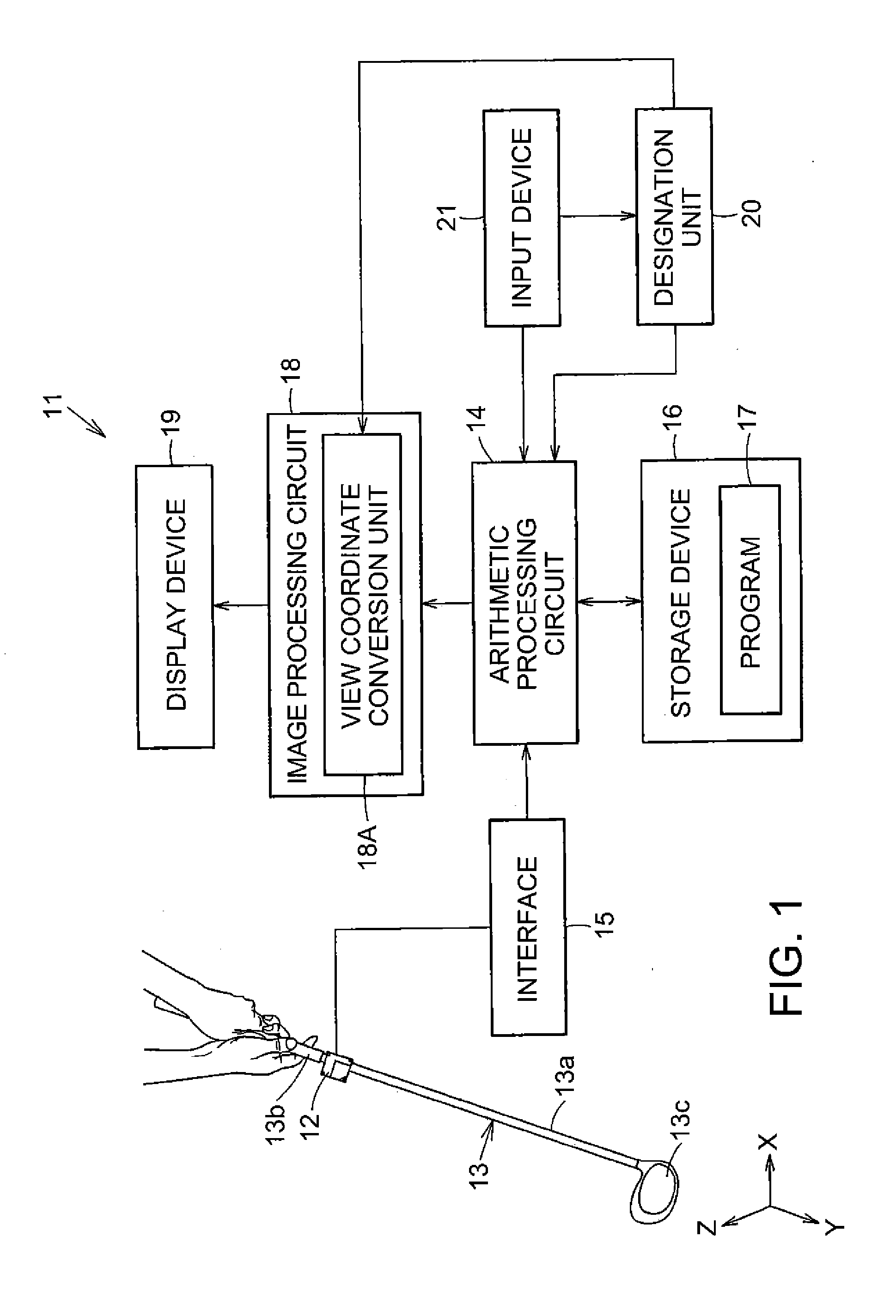
[0038]FIG. 1 schematically illustrates the configuration of a golf swing analysis apparatus (movement analysis apparatus) 11 according to an embodiment of the invention. The golf swing analysis apparatus 11 includes, for example, an inertial sensor 12. The inertial sensor 12 is provided with, for example, an acceleration sensor and a gyro sensor. The acceleration sensor is capable of detecting respective accelerations in triaxial directions which are perpendicular to each other. The gyro sensor is capable of individually detecting respective angular velociti...


PUM


Abstract

A designation unit designates a checkpoint of sporting equipment on which a swing motion is performed. A first calculation unit calculates a movement path of the sporting equipment, which is being swung, using an output of an inertial sensor. A second calculation unit calculates a posture of an interest part of the sporting equipment at the checkpoint using the output of the inertial sensor up to the checkpoint on the movement path of the sporting equipment. The display unit displays the posture of the interest part of the sporting equipment at the checkpoint.

Description

CROSS REFERENCE[0001]The entire disclosure of Japanese Patent Application No. 2013-217642, filed Oct. 18, 2013, is expressly incorporated by reference herein.BACKGROUND[0002]1. Technical Field[0003]The present invention relates to a movement analysis method, a movement analysis apparatus, and a movement analysis program.[0004]2. Related Art[0005]A movement analysis apparatus is used for analysis of a movement called a swing motion. An inertial sensor is mounted on sporting equipment or an examinee who operates the sporting equipment. The swing motion is visually reproduced based on output of the inertial sensor. As a detailed example of the movement analysis apparatus, for example, a golf swing analysis apparatus which is disclosed in JP-A-2008-73210 may be shown.[0006]In golf, the direction of a struck ball is greatly affected by the direction of a face of a club head at an impact moment. As known, when trying to align the face of the club head by twisting the wrist immediately bef...

Claims


Application Information

Patent Timeline
IPC IPC(8): A63B24/00A63B69/36
CPCA63B24/0006A63B2220/803A63B2220/833A63B69/3632G09B19/0038G06V40/23
Inventor SHIBUYA, KAZUHIRONOMURA, KAZUOKODAIRA, KENYASATO, MASAFUMI
Owner SEIKO EPSON CORP
Why Eureka
Try Eureka