
Display System, Display Device, And Display Method

a display system and display device technology, applied in the field of display systems and display devices, can solve the problems of difficult to determine which client devices, and the limited operation of receiving devices receiving data, and achieve the effect of high degree of freedom

Inactive Publication Date: 2015-04-23
SEIKO EPSON CORP
View PDF7 Cites 3 Cited by
  • Summary
  • Abstract
  • Description
  • Claims
  • Application Information

AI Technical Summary

Benefits of technology

The present invention allows for more freedom in controlling the relationship between devices when communicating data. This is achieved by linking the storage display of the second device to a storage area of the first device, which can influence the correlation between the devices. The degree of freedom is increased when data is sent and received between multiple devices. Additionally, this configuration simplifies sending data to devices with display units.

Problems solved by technology

However, when data is transmitted without the device on the side that receives the data asserting a request for the data, it is not easy to determine which client device the data should be sent to because the receiving side does not request the data.
The operations that can be performed when the receiving device receives the data may also be limited.

Method used


Image

  • Display System, Display Device, And Display Method
  • Display System, Display Device, And Display Method
  • Display System, Display Device, And Display Method

Examples


Embodiment Construction

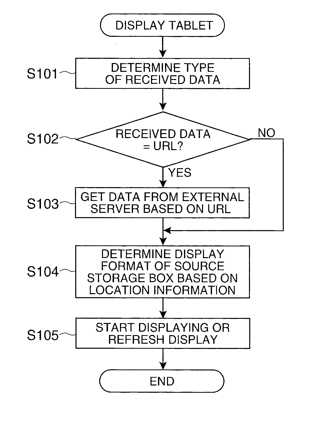
[0051]A preferred embodiment of the present invention is described below with reference to the accompanying figures.

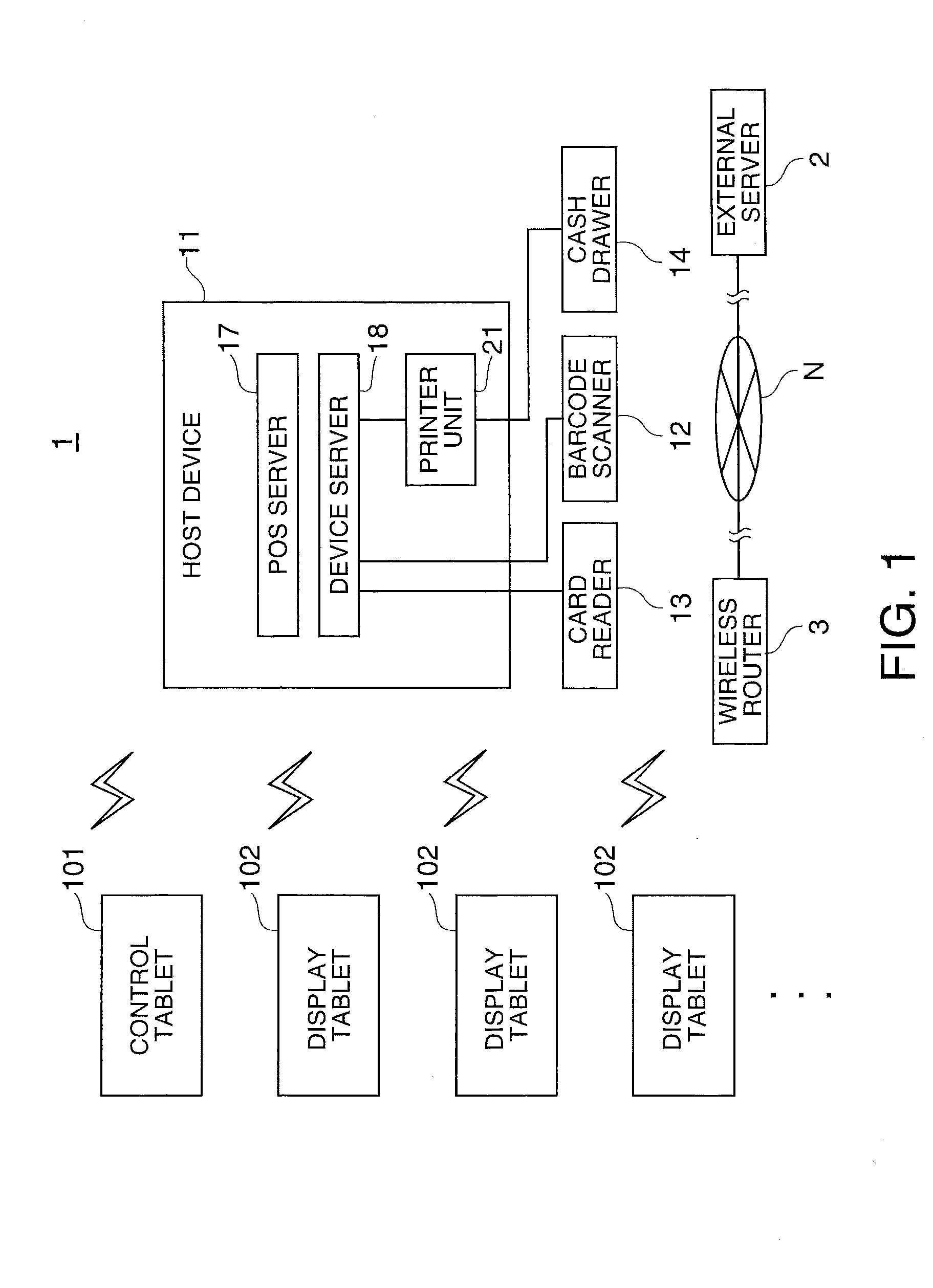
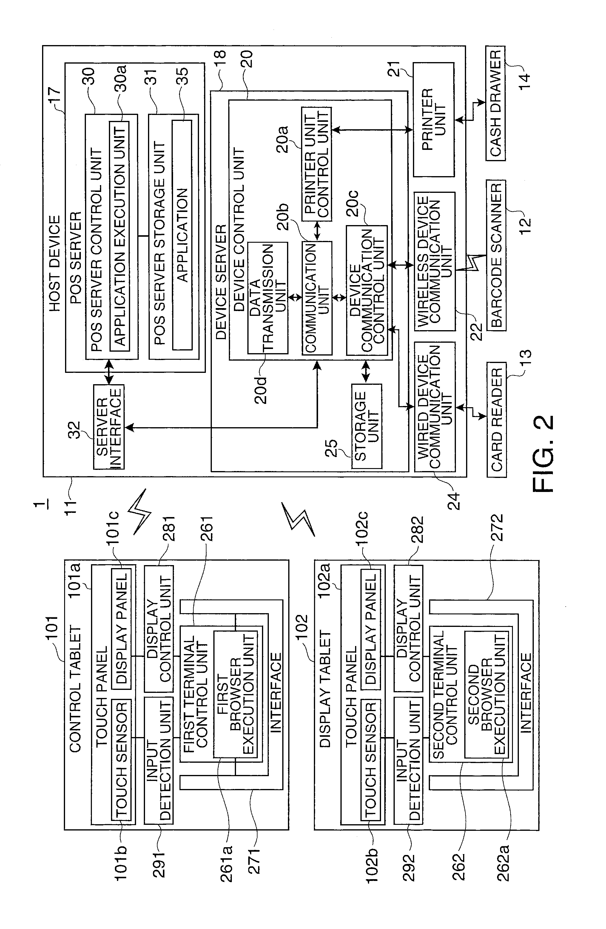
[0052]FIG. 1 is a block diagram illustrating an example of the basic configuration of a POS (point-of -sale) system 1 (display system) according to this embodiment of the invention. FIG. 2 is a block diagram exemplarily illustrating the functional configuration of a control tablet 101, a display tablet 102, and a host device 11.

[0053]The POS system 1 executes a data process, to process product sales data in a store or other facility such as a retail store, restaurant or bar, or a service provider, for example. The data processes include, for example, registering products, calculating invoice amounts, transaction processes accompanying payment, issuing receipts showing the content of a transaction process, and providing information related to transaction processes. The POS system 1 manages product sales, product inventory, and sales information.

[0054]In one example, the...


PUM


Abstract

The correlation between a device on the sending side and a device on the receiving side can be controlled with a high degree of freedom when sending and receiving data between multiple devices. A POS system 1 includes a host device 11 with a storage unit 25 having a data storage box 26 that stores data, and a transmission unit that sends data the data storage box 26 stores when data is stored in the data storage box 26; and a display tablet 102 that receives and displays data sent by the host device 11. The display panel 102c of the display tablet 102 is linked to the data storage box 26 of the storage unit 25 of the host device 11.

Description

CROSS-REFERENCE TO RELATED APPLICATION(S)[0001]Priority is claimed under 35 U.S.C. §119 to Japanese Application nos. 2013-218962, filed Oct. 22, 2013 and 2013-218963, filed Oct. 22, 2013, which are hereby incorporated by reference in their entirety.BACKGROUND[0002]1. Technical Field[0003]The present invention relates to a display system, a display device, and a display method.[0004]2. Related Art[0005]Two-way communication using the WebSocket standard is one method of exchanging data between a plurality of devices as described in JP-A-2012-182744. Each time data is stored in the storage unit of the server in the configuration disclosed in JP-A-2012-182744, the server sends the data to a client device. Thus comprised, data can be transmitted without the client device requesting data from the server.[0006]However, when data is transmitted without the device on the side that receives the data asserting a request for the data, it is not easy to determine which client device the data sho...

Claims


Application Information

Patent Timeline
IPC IPC(8): G06T1/20
CPCG06T1/20G07G1/14G06F3/14G09G2380/06H04L67/02H04L67/025H04L67/08H04L67/1095
Inventor AOKI, SHIGERUKANEKO, NAOHIRO
Owner SEIKO EPSON CORP
Learn More