
System for inventory tracking and monitoring using a database of low-power active tags and a method for its use

a low-power active tag and inventory tracking technology, applied in the field of inventory organizing systems, can solve the problems of inability to initiate communication or engage in complex processing, the range of tags currently available is also inherently very limited, and the cost, power and flexibility of tags are not ideal combinations

Inactive Publication Date: 2015-04-16
HEALTHVENTIVE
View PDF1 Cites 12 Cited by
  • Summary
  • Abstract
  • Description
  • Claims
  • Application Information

AI Technical Summary

Benefits of technology

The patent describes a system and method for inventory monitoring and tracking using tags and a hub. The tags have a very low duty cycle and a low duty cycle, and can switch between them. The system includes a database, a transceiver, a memory, and a microprocessor. The tags can communicate with the hub using different radio frequencies. The system can also include sensors and additional tags. The method involves listening for commands, receiving commands, and executing them. The system can also authenticate passphrases and commands. The technical effects of the system and method include improved inventory monitoring and tracking, reduced power consumption, and improved security.

Problems solved by technology

Little doubt exists that the geometric connectivity of devices, such as tags, available via the Internet will be the next frontier of enormous growth, subject to the ability to manage security, privacy, power and cost.
However, the tags currently available do not present an ideal combination of cost, power, and flexibility.
Passive tags, which rely on an interrogating device to induce currents in their circuitry, can only act in reaction to interrogation, and thus lack the ability to initiate communication or engage in complex processing.
The range of such tags is also inherently very limited.
Active tags, which have their own power source, can do what passive tags cannot, but quickly consume power, and thus battery life.

Method used


Image

  • System for inventory tracking and monitoring using a database of low-power active tags and a method for its use
  • System for inventory tracking and monitoring using a database of low-power active tags and a method for its use
  • System for inventory tracking and monitoring using a database of low-power active tags and a method for its use

Examples


Embodiment Construction

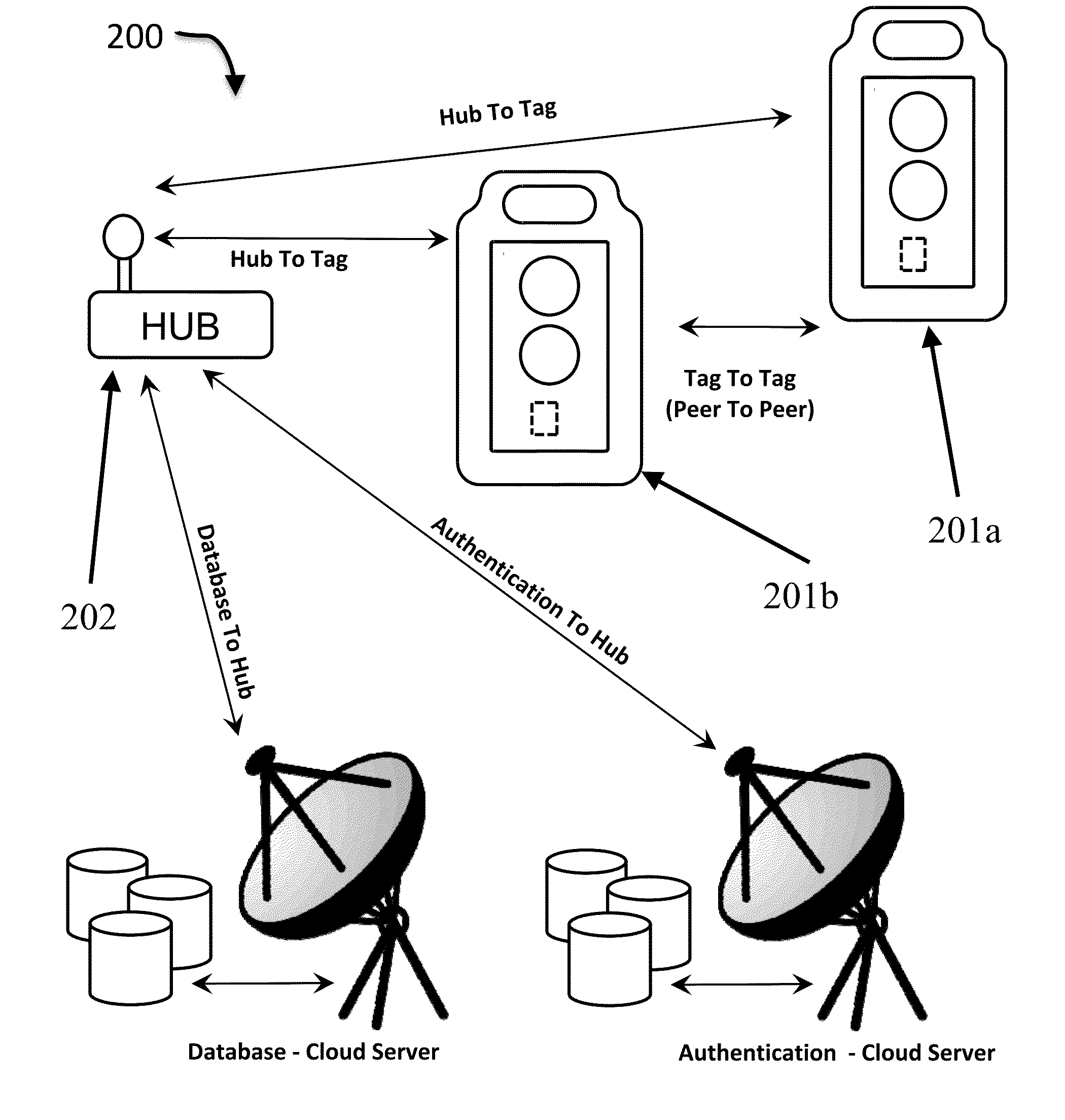
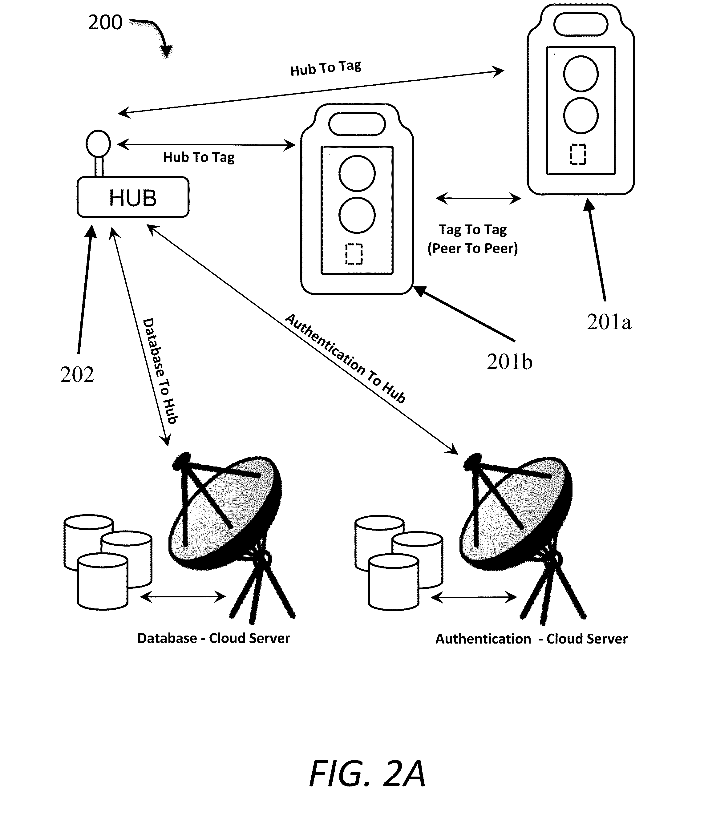
[0006]A system is disclosed for inventory monitoring and tracking, including at least one tag having a very low duty cycle, a low duty cycle, a transceiver, a memory and a microprocessor configured to switch between the very low duty cycle and the low duty cycle, to transmit and receive signals via the transceiver, to read data from the memory, and to write data to the memory, and at least one hub having a radio frequency communication device configured to communicate with the at least one tag.

[0007]In a related embodiment of the system, the at least one tag is configured to communicate on a first radio frequency when operating in the very low duty cycle, and on a second, distinct radio frequency while operating in the low duty cycle. Another embodiment includes a database accessible to the at least one hub. An additional embodiment includes a signaling facility coupled to the at least one tag. In another embodiment, the system includes at least one sensor coupled to the at least on...


PUM


Abstract

Described herein is a device and system for very low power wireless communication between small transceivers, which are applied to objects and remote databases or programs. The disclosed device and system requires so little energy that ordinary inexpensive coin cells can power a transceiver for many years. The system disclosed herein gives the benefits of true bi-directional interactive communication but at a very low cost and power requirement. The ability of the transceiver to respond using its own power source represents a fundamental advance in the state of the art over traditional RFID methods.

Description

RELATED APPLICATION DATA[0001]This application claims the benefit of Provisional Application No. 61 / 889,051, filed on Oct. 10, 2013.TECHNICAL FIELD[0002]Embodiments disclosed herein relate generally to systems for organizing inventory, and in particular to the organization of inventory using radio frequency identification technology.BACKGROUND ART[0003]There is substantial interest in and numerous applications for the ability to allow collections of information, hereinafter referred to as “Databases”, to interact with and communicate with small inexpensive devices to signal conditions or alerts to people. Such small devices with the features of signaling, storage, and wireless communication are hereinafter referred to as “tags”. Little doubt exists that the geometric connectivity of devices, such as tags, available via the Internet will be the next frontier of enormous growth, subject to the ability to manage security, privacy, power and cost.[0004]However, the tags currently availa...

Claims


Application Information

Patent Timeline
Patent Type & Authority Applications(United States)
IPC IPC(8): G06K7/10G07C9/00G06Q10/08
CPCG06K7/10366G06Q10/087G07C9/00103G07C9/27
Inventor HEIM, THOMASSCHLANGER, STEVEN ERIC
Owner HEALTHVENTIVE
Learn More