
Connection structure for ground terminal fitting

a technology for connecting structures and ground terminals, which is applied in the direction of vehicle connectors, electrical devices, coupling device connections, etc., can solve the problems of difficult positioning of ground terminals with respect to ground panels, and achieve the effect of reducing the load on the receiving portion and the locking portion

Active Publication Date: 2015-04-09
SUMITOMO WIRING SYST LTD
View PDF9 Cites 7 Cited by
  • Summary
  • Abstract
  • Description
  • Claims
  • Application Information

AI Technical Summary

Benefits of technology

The invention is a locking mechanism for a wire used in a device. The locking portion is located on the wire's axis, making it easy for an operator to grip and position. The locking direction is parallel to the wire's axial direction, making it easy to lock. The locking portion and receiving portion can contact each other to prevent rotation of the terminal main body when a bolt is tightened. The distance between the receiving portion and the first female screw hole is set longer than the distance between the receiving portion and the second female screw hole to reduce loads on the receiving portion and locking portion.

Problems solved by technology

However, positioning the ground terminal with respect to the ground panel is difficult with a connection structure that has a female screw hole provided on a ground panel and a through hole of a ground terminal positioned with respect to the female screw hole.
However, this approach presents a new problem of positioning the lock and the receiving portion prior to locking the lock to the receiving portion.

Method used


Image

  • Connection structure for ground terminal fitting
  • Connection structure for ground terminal fitting
  • Connection structure for ground terminal fitting

Examples


Embodiment Construction

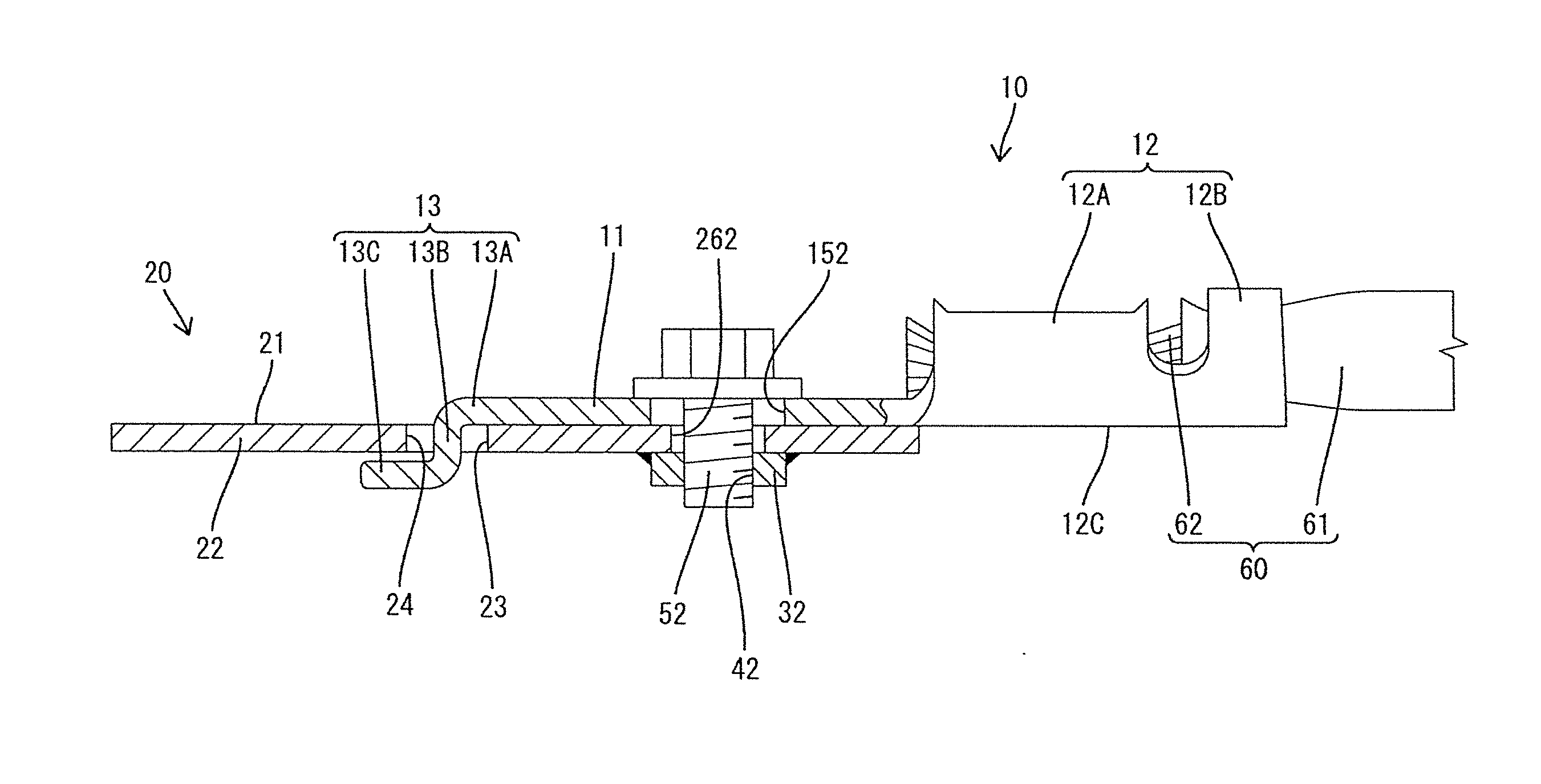
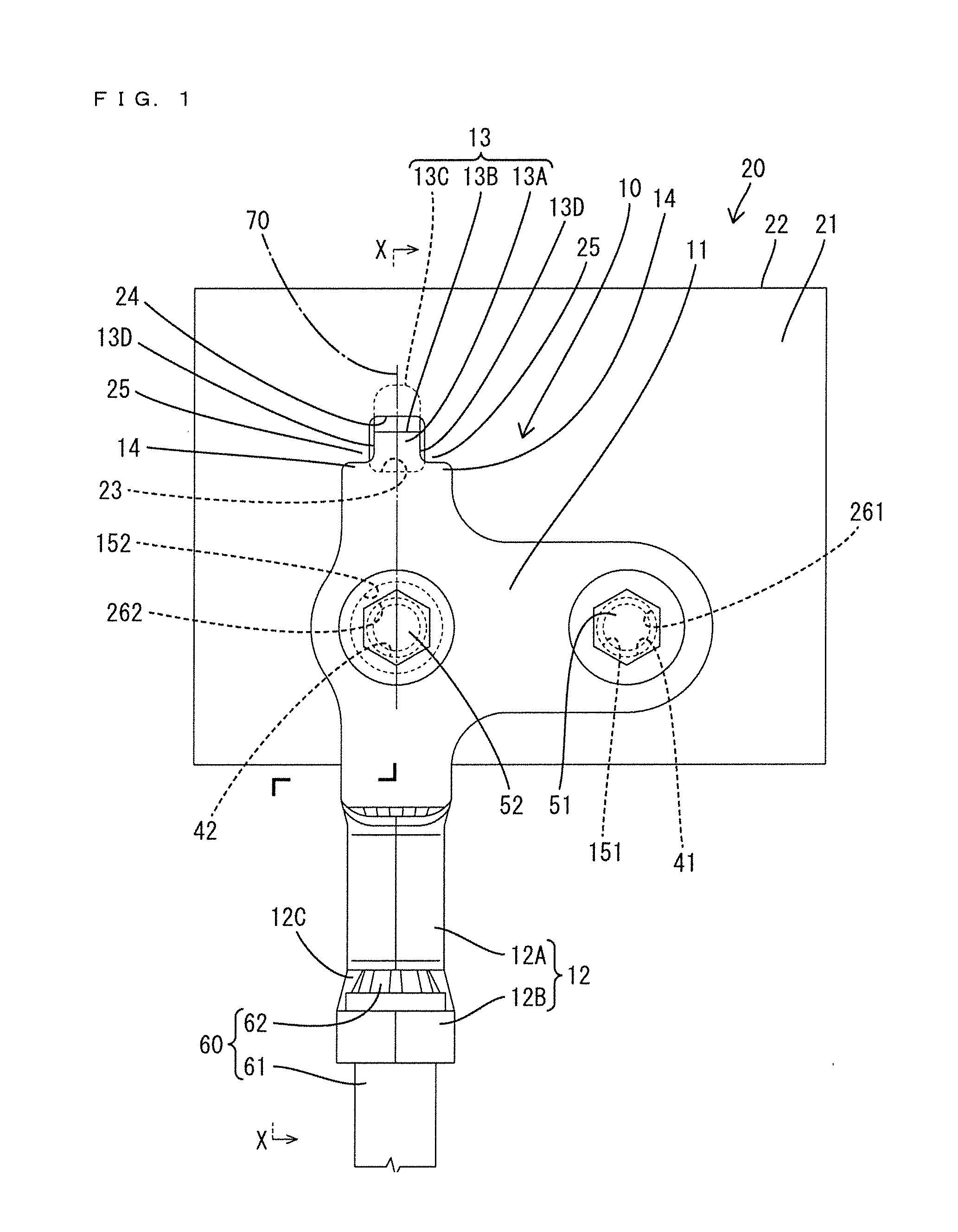
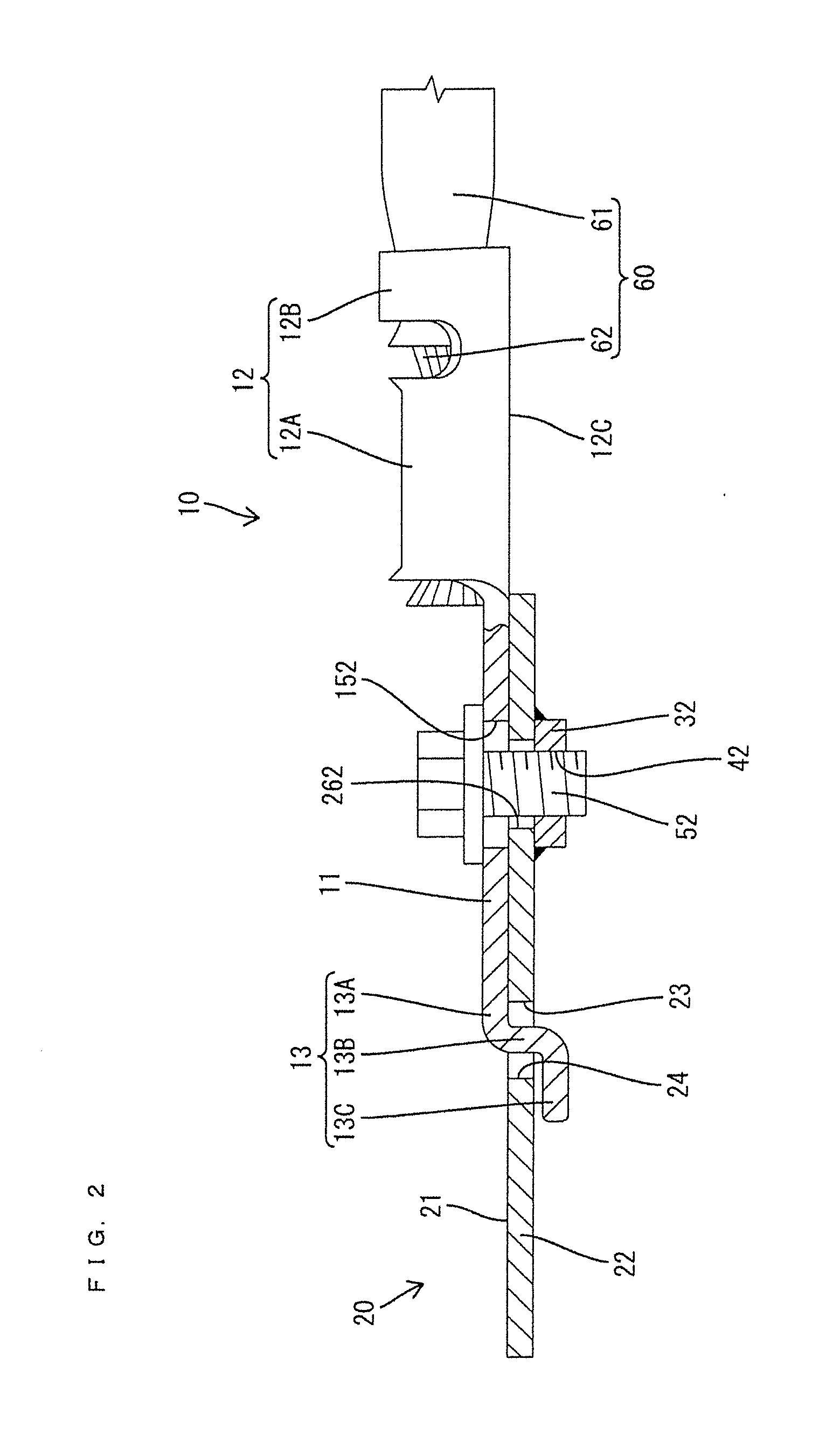
[0020]A connection structure for a ground terminal fitting is identified by the numeral 10 in FIGS. 1 to 7 and is configured for fixing and electrically conductively connecting the ground terminal fitting 10 in surface contact with a ground contact surface 21 of a grounding member 20 such as a body of a vehicle. Note that, an upper side in FIGS. 1, 3 to 6 is defined as a “front” concerning a front-back direction. Further, a vertical direction is based on FIGS. 2 and 7 and a lateral direction is based on FIGS. 1, 3 to 6.

[0021]As shown in FIGS. 2 and 5, the grounding member 20 includes a panel 22 in the form of a flat metal plate. A first metal nut 31 is fixed electrically conductively to the lower surface of the panel 22, such as by welding and a second metal nut 32 is fixed electrically conductively to the lower surface of the panel 22, such as by welding. The upper surface of the panel 22 defines the ground contact surface 21 for electrically conductive connection to the ground ter...


PUM


Abstract

A connection structure connects a plate-like terminal main body (11) on the ground terminal fitting (10) in surface contact with a grounding member (20) that has female screw holes (41, 42) and a receiving portion (23). A wire connecting portion (12) on the ground terminal fitting (10) is connected to a wire (60). A lock (13) on the terminal main body (11) engages the receiving portion (23) and is on an axis line extension (70) of the wire (60). Mounting holes (151, 152) formed on the terminal main body (11) and aligned with the female screw holes (41, 42) by locking the lock (13) to the receiving portion (23). The ground terminal fitting (10) is connected to the grounding member (20) by screwing bolts (51, 52) inserted through the mounting holes (151, 152) into the female screw holes (41, 42).

Description

BACKGROUND[0001]1. Field of the Invention[0002]The present invention relates to a connection structure for ground terminal fitting.[0003]2. Description of the Related Art[0004]Japanese Unexamined Patent Publication No. 2004-253167 discloses a connection structure for fitting and connecting through holes of a ground terminal to two stud bolts projecting on a ground panel. The connection structure that has stud bolts projecting on the ground panel easily positions the ground terminal with respect to the ground panel. However, positioning the ground terminal with respect to the ground panel is difficult with a connection structure that has a female screw hole provided on a ground panel and a through hole of a ground terminal positioned with respect to the female screw hole.[0005]Consideration has been given to providing a lock on the ground terminal for locking to a receiving portion formed on the ground panel to facilitate positioning the ground terminal. However, this approach presen...

Claims


Application Information

Patent Timeline
IPC IPC(8): H01R4/30
CPCH01R4/305H01R11/12H01R2201/26
Inventor NOBUKUNI, TAKASHI
Owner SUMITOMO WIRING SYST LTD
Learn More