Dynamic route branching system and dynamic route branching method

a branching system and dynamic technology, applied in the field of dynamic route branching system, can solve the problems of difficult to dynamically adopt a multi-path route, difficult to select an identical copy, difficult to adopt the dynamic optimal design, etc., and achieve the effect of improving the traffic reception performance of the reception terminal

Active Publication Date: 2015-04-02
NEC CORP
View PDF6 Cites 3 Cited by
  • Summary
  • Abstract
  • Description
  • Claims
  • Application Information

AI Technical Summary

Benefits of technology

[0029]Even if a phenomenon that a traffic flow is discarded in a main route due to the change of state in the network occurs, the whole traffic is quickly restored by using the traffic on the sub-route, so as to improve the traffic reception performance of the reception terminal.

Problems solved by technology

(1) It was difficult to dynamically adopt a multipath route according to the reception situation of the traffic of each terminal.
(2) When adopting the multipath route, it was difficult to select an identical copy (full mirroring) and a partial copy (partial mirroring), a flow base division, a random division and so on in a split position according to the situation of the network.
(3) It was difficult to adopt the dynamic optimum design so as to minimize the cost imposed on the network by taking a multipath route.
However, it is difficult to set a plurality of routes in an optional position, and the route is selected in a flow base by the Hash function in the split position of the multipath.
Therefore, it is difficult to control according to the reception situation of the traffic of each terminal.
However, the multipath can not be generated from a node on the way of the network and it is difficult to control according to the reception situation of the traffic of each terminal.
In this method, communication is switched to the photonic network when detecting a large amount of traffic, because enough performance can not be attained in a large capacity communication of the IP network.
However, as mentioned above, because there is not a function of branching in the optional position in the network in a conventional method, there is no technique for maximizing reception performance of the terminal.

Method used


Image

  • Dynamic route branching system and dynamic route branching method
  • Dynamic route branching system and dynamic route branching method
  • Dynamic route branching system and dynamic route branching method

Examples


first exemplary embodiment

[0058]Next, the first exemplary embodiment of the present invention will be described.

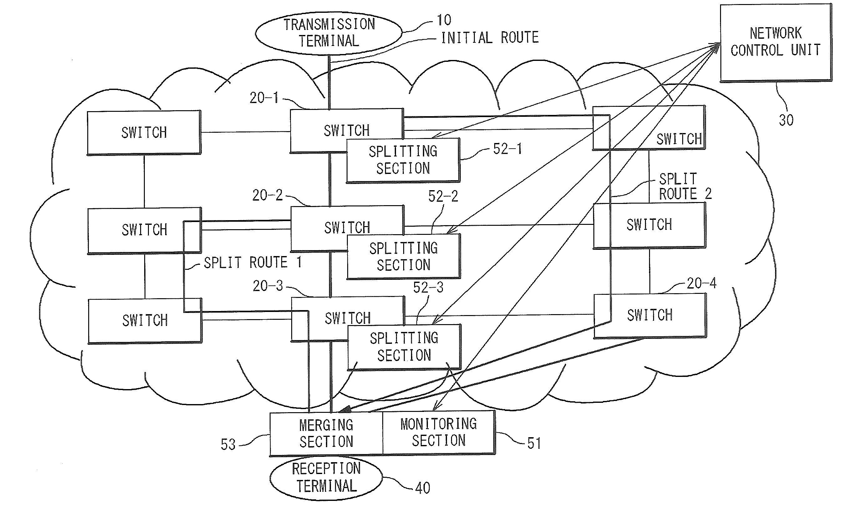
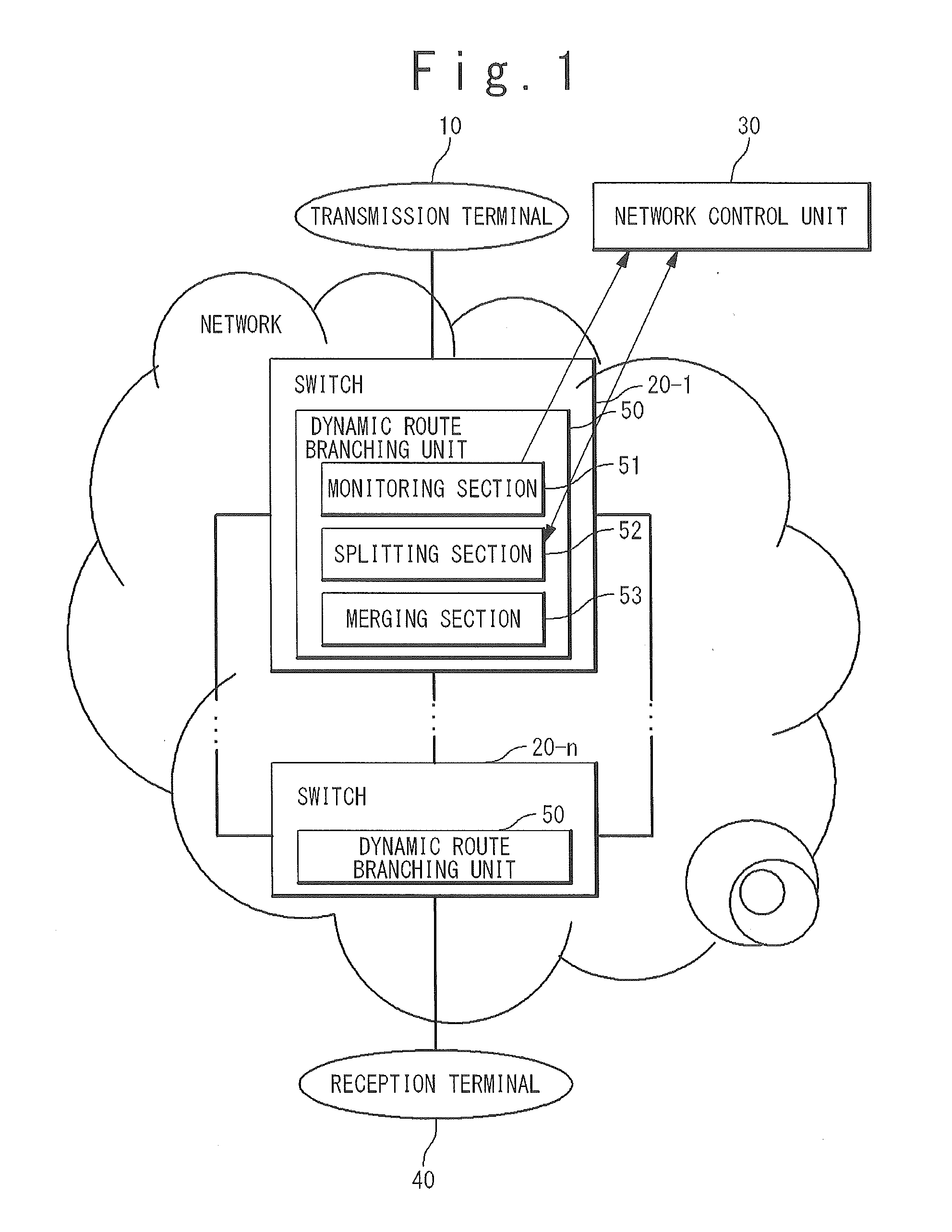
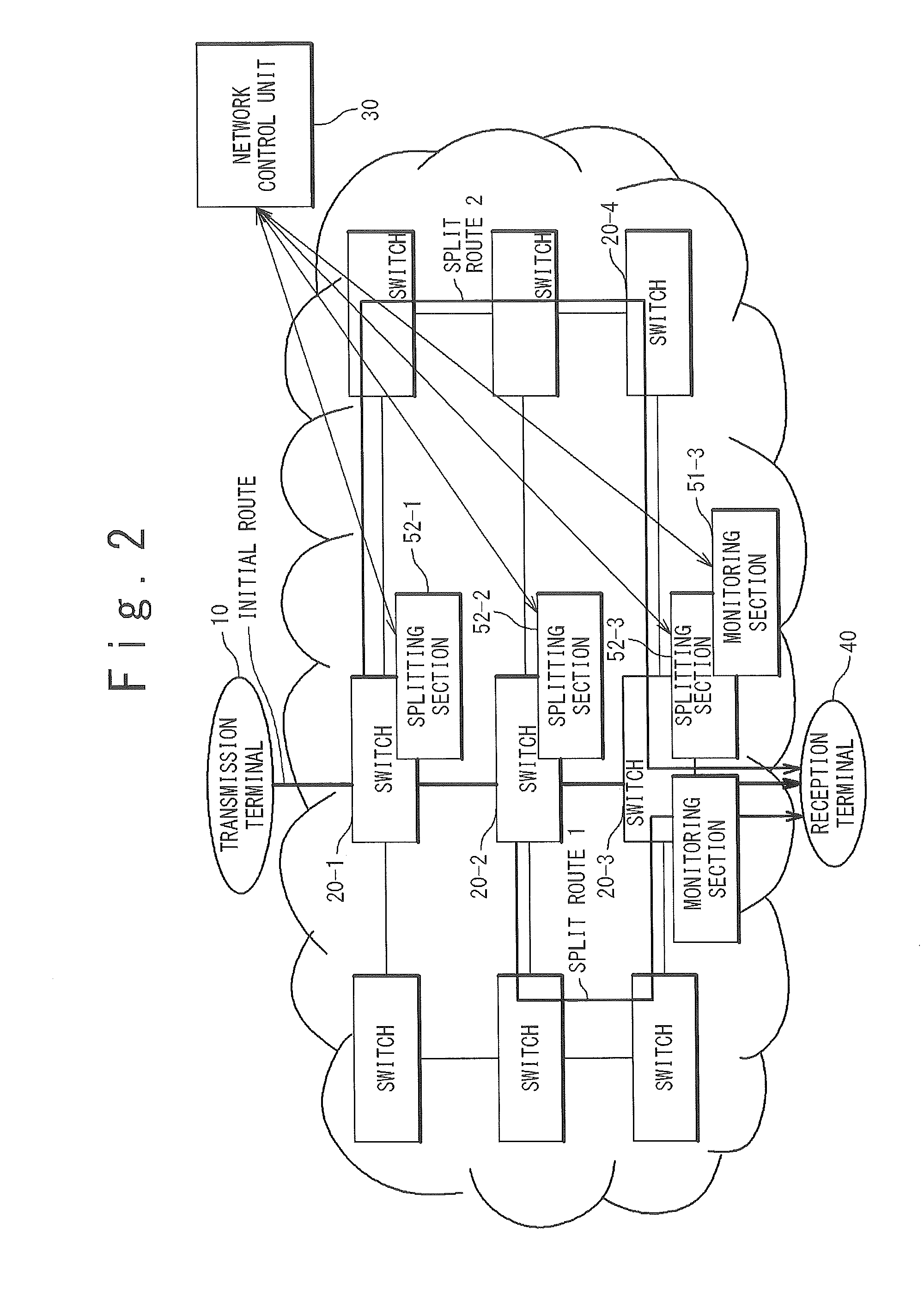
[0059]In the present exemplary embodiment, as shown in FIG. 2, a case in which a monitoring process is executed only in the switch (Egress switch) 20 at the last stage which is the nearest to the reception terminal 40, of the switches 20 (20-i, i=1 to n) in the network will be described. In the present exemplary embodiment, the monitoring section 51 and the merging section 53 are provided in the switch (Egress switch) 20 at the last stage, and the splitting section 52 is provided in optional switches 20. That is, the monitoring section 51 and the merging section 53 function only in the switch (Egress switch) 20 at the last stage, and the splitting section 52 functions in all the switches of the network.

[0060]In an example of FIG. 2, the monitoring section 51 monitors the network quality of the traffic which is transmitted on an initial route from the transmission terminal 10 to the reception termin...

case 1

(Case 1)

[0064]First, a case of “the identical copy (model A) / the partial copy (model B)” will be described.

[0065]For example, when the load is high as the whole network and a loss in the network occurs in any route, or when the network is unstable so as to require a long time for restoration in case of a fault occurrence in the network, the network control unit 30 instructs the splitting section 52 to execute the identical copy (model A) or the partial copy (model B).

(Identical Copy)

[0066]In case of the identical copy, the splitting section 52 copies the entire traffic flow unconditionally and transmits them by a plurality of routes such as the initial route and a detour route (a split route). In the switch (egress switch) 20 at the last stage on the side of the reception terminal 40, the merging section 53 discards an overlapping portion from the traffic flows transmitted through the plurality of routes such as the initial route and the detour route to restore the right traffic flo...

case 2

(Case 2)

[0070]Next, a case of “flow base division / random division (model C)” will be described.

[0071]For example, when few bands exist on the whole network in a traffic system in which the loss in the whole network does not cause a problem, the network control unit 30 instructs the splitting section 52 to execute the flow base division (model C) or the random division (model C).

(Flow Base Division)

[0072]In case of the flow base division, the splitting section 52 changes the route every flow group based on flow data. In the switch (Egress switch) 20 at the last stage on the side of the reception terminal 40, the merging section 53 receives all the flow groups and transmits to the reception terminal 40.

(Random Division)

[0073]In case of the random division, the splitting section 52 changes the route randomly every packet. For example, the splitting section 52 alternately / randomly distributes the received packets to two split routes and transmits them. The same thing is applied in case ...


PUM


Abstract

A system that includes a plurality of nodes to forward a data packet in a network, includes a controller to select at least a node dividing a data path of the data packet into a first path and a second path, from the nodes, based on a condition of the data path, and a node selected by the controller being capable of forwarding the packet to the first path and the second path according to an instruction from the controller. The second path includes a bypass path of the first path.

Description

[0001]The present application is a Continuation application of U.S. patent application Ser. No. 13 / 510,622, filed on May 17, 2012, which is based on International Application No. PCT / JP2010 / 070208, filed on Nov. 12, 2010, which is based on and claims priority from Japanese patent application No. 2009-263342, filed on Nov. 18, 2009, the entire contents of which are incorporated herein by reference.TECHNICAL FIELD[0002]The present invention is related to a dynamic route branching system, and especially, to a dynamic route branching system in a network which adopts a multipath route communication.BACKGROUND ART[0003]Conventionally, there were the following problems (1)-(3) in case of multipath route communication to improve the communication when the traffic is discarded in a network due to an insufficient link band width on a route in the network.[0004](1) It was difficult to dynamically adopt a multipath route according to the reception situation of the traffic of each terminal.[0005...

Claims


Application Information

Patent Timeline
Patent Type & Authority Applications(United States)
IPC IPC(8): H04L12/707H04L12/26H04L45/24
CPCH04L43/10H04L45/24H04L45/00H04L12/28
Inventor IWATA, ATSUSHIIIJIMA, AKIO
Owner NEC CORP
Why Eureka
Try Eureka