Eureka AIR delivers breakthrough ideas for toughest innovation challenges, trusted by R&D personnel around the world.

Real-time wireless power transfer control for passive backscattering devices

a backscattering device and real-time wireless technology, applied in the field of wireless power transfer, can solve the problems of increasing the transmission power of the interrogator (reader), and reducing the transmit power of the interrogator (reader)

Active Publication Date: 2015-04-02
RICOH KK +1
View PDF4 Cites 285 Cited by
  • Summary
  • Abstract
  • Description
  • Claims
  • Application Information

AI Technical Summary

Benefits of technology

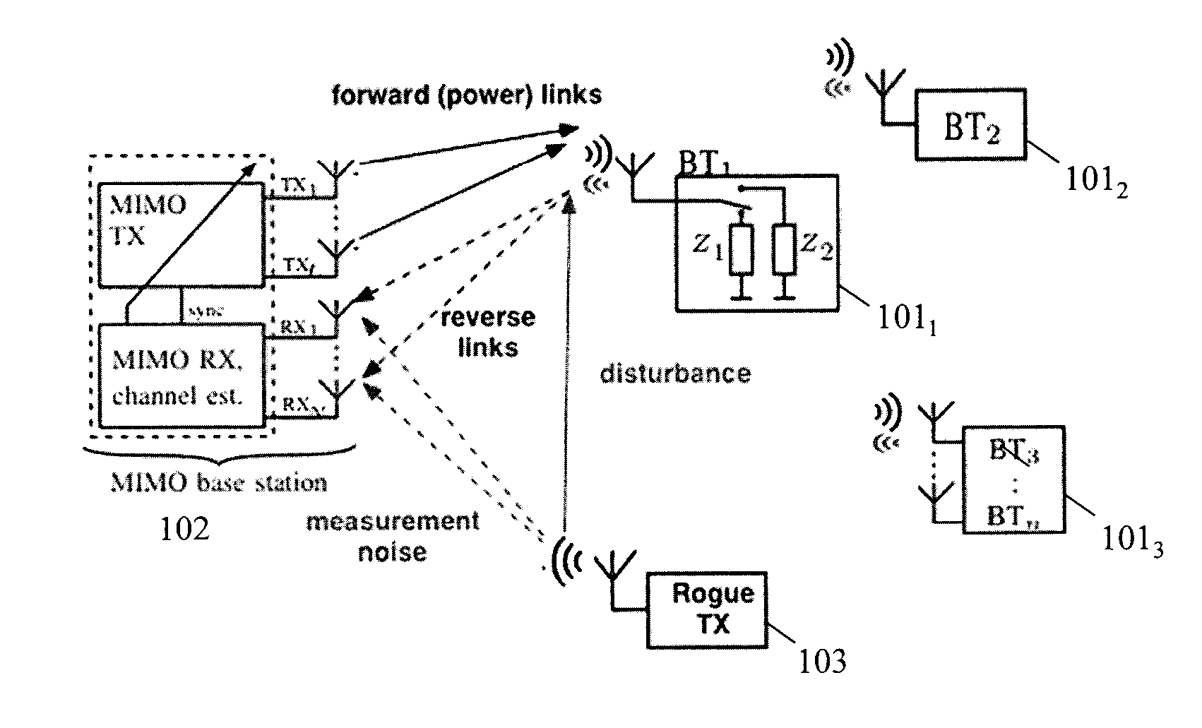
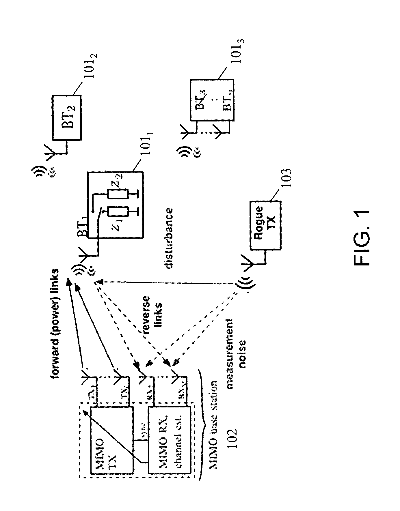
The patent is about a method and device for controlling the transfer of wireless power in real-time. It involves a sensor tag that generates a signal by scattering a waveform of RF energy, and a base station that delivers power to the sensor tag using the scattered signal. The sensor tag then emits a new signal that is responsive to feedback control from the base station. This results in a more efficient transfer of power, based on the sensor tag's feedback on the previous power transfer. The technical effect of this patent is improved real-time wireless power transfer control.

Problems solved by technology

Standard passive (battery-less) RFID tags provide no means of acquiring sensor information when they are outside the communication range of a reader.
Increasing the amount of incident power at transponder is an important problem, as it typically leads to the increase in both the harvestable energy, and the energy available for communications (backscatter).
However, the transmit power of the interrogators (readers), is ultimately limited because of regulations imposed by regulatory bodies (the FCC in case of the USA), capping the emitted RF power at certain levels specific to each RF band.
Also, increasing the transmit power is not the most efficient approach in case of multipath environment, or in face of a highly nonlinear behavior of the harvester element (such as one or more diodes or diode-connected transistors) of the transponder device, as it precludes selective manipulation of power delivered to transponders.

Method used


Image

  • Real-time wireless power transfer control for passive backscattering devices
  • Real-time wireless power transfer control for passive backscattering devices
  • Real-time wireless power transfer control for passive backscattering devices

Examples


Embodiment Construction

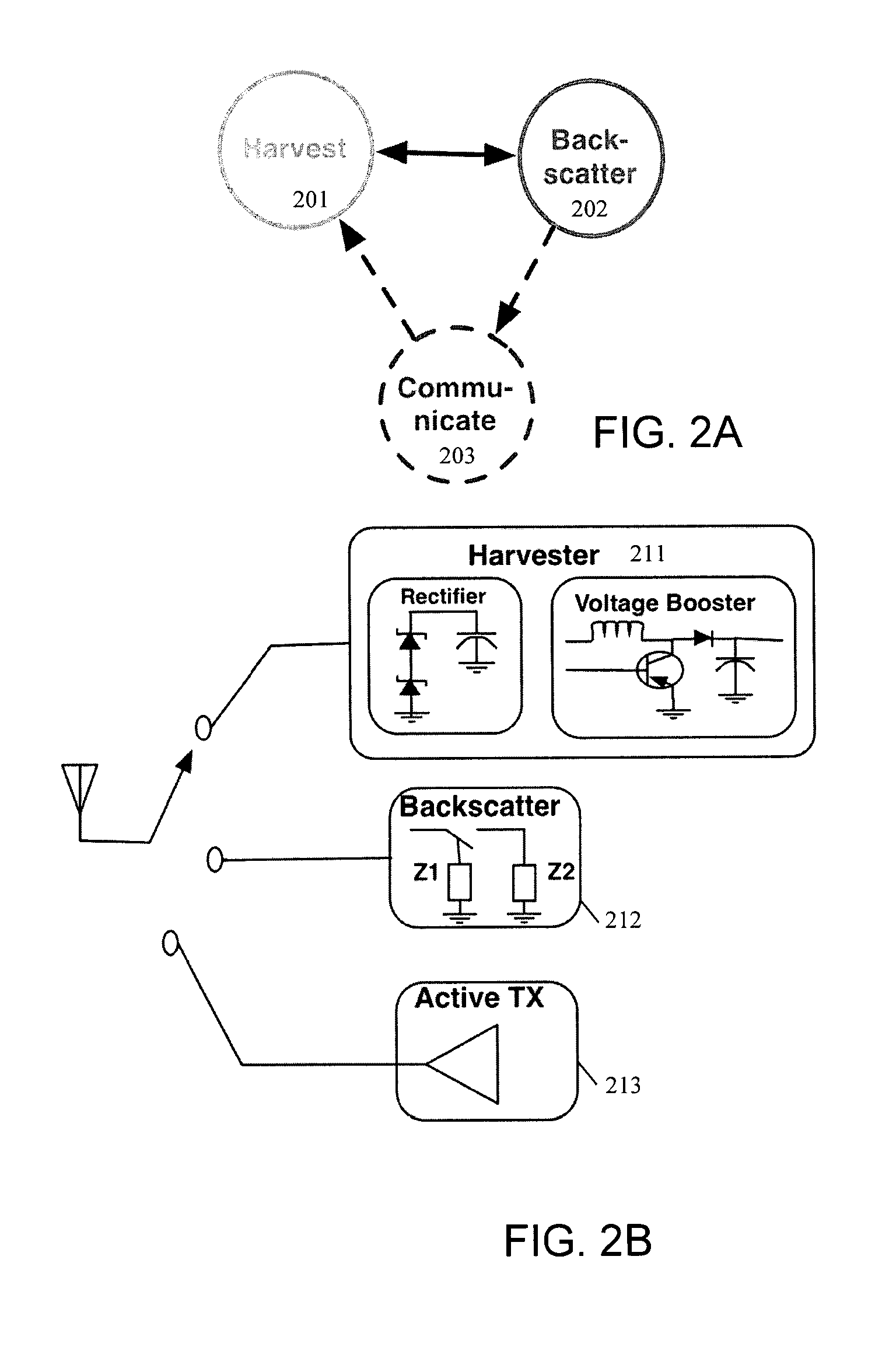
[0026]Embodiments of the present invention include RF tags and components in wireless communication systems (e.g., Wi-Fi communication systems) that provide power to such tags. The tags perform RF energy harvesting and include a backscatter transponders which provide an indirect indication of the RF power incident upon that tag. Such tags may be part of a sensor network. In one embodiment, the tags perform energy harvesting, collect and process sensor data, and communicate data using standard RF communication techniques (e.g., Wi-Fi).

[0027]In the following description, numerous details are set forth to provide a more thorough explanation of the present invention. It will be apparent, however, to one skilled in the art, that the present invention may be practiced without these specific details. In other instances, well-known structures and devices are shown in block diagram form, rather than in detail, in order to avoid obscuring the present invention.

[0028]Some portions of the detai...


PUM


Abstract

A method and apparatus is disclosed herein for real-time wireless power transfer control. In one embodiment, a system comprises: an RF-energy harvesting sensor tag operable to generate a first backscatter signal and at least one base station operable to deliver RF power to the sensor tag by emitting a first waveform comprising a plurality of subcarriers, wherein the first backscatter signal is generated by the sensor tag by modulated scattering of the first waveform as incident upon the sensor tag, and further wherein the at least one base station subsequently emits a second waveform determined at least in part by a closed-loop feedback control algorithm responsive to measurements of the first backscatter signal.

Description

FIELD OF THE INVENTION[0001]Embodiments of the present invention relate to the field of wireless power transfer; more particularly, embodiments of the present invention relate to wireless power transfer for passive backscattering devices (e.g., RF energy harvesting sensor nodes with backscatter capabilities).BACKGROUND OF THE INVENTION[0002]Radio Frequency Identification (RFID) tags are becoming increasingly common. RFID tags that include sensing capabilities have emerged as a generally inexpensive and effective means of addressing many wireless sensor applications in both indoor and outdoor sensing applications. Purely passive sensors, such as RFID tags, when actively interrogated by an RF transceiver / reader, receive energy to power themselves up so that they can acquire readings from their attached sensing elements. Generally, RFID tags equipped with one or more sensors require a source of energy to measure and store their acquired information at times other than during active int...

Claims


Application Information

Patent Timeline
IPC IPC(8): G06K7/10H02J17/00H02J5/00
CPCG06K7/10158H02J17/00H02J5/005H02J50/20H02J50/70
Inventor CHEMISHKIAN, SERGEYARNITZ, DANIELREYNOLDS, MATTHEW S.
Owner RICOH KK
Why Eureka
Eureka Blog
Learn More