
Alternating current (AC) power flow analysis in an electrical power network

a technology of ac power flow and electrical power network, applied in the field of computer-implemented methods for ac power flow analysis in electrical power network, can solve the problems of new challenges in the planning and control of electrical power system, and achieve the effect of reducing the cost of generating electricity

Active Publication Date: 2015-03-26
NAT ICT AUSTRALIA
View PDF6 Cites 30 Cited by
  • Summary
  • Abstract
  • Description
  • Claims
  • Application Information

AI Technical Summary

Benefits of technology

The patent text is about a method called AC optimal power flow that is used to manage electricity in power networks. The goal is to minimize the cost of generating electricity by finding the best way to use the available resources. This can help to improve the efficiency of the network and save money for users.

Problems solved by technology

However, the increasing role of demand response, the integration of renewable sources of energy, and the desire for more automation in fault detection and recovery pose new challenges for the planning and control of electrical power systems.

Method used


Image

  • Alternating current (AC) power flow analysis in an electrical power network
  • Alternating current (AC) power flow analysis in an electrical power network
  • Alternating current (AC) power flow analysis in an electrical power network

Examples


case study 1

(a) Optimal Power Flow

[0287]The goal of the optimal power flow problem (OPF) is to find the cheapest way to generate power in order to satisfy customers' demand given some quadratic cost functions on generators. For each generator n E G, the cost of generating power is defined by the quadratic function cn″(png)2+cn′(png)+cn. A classic OPF problem consist of minimizing the generation cost Σn∈Gcn″(png)2+cn′(png)+cn subject to the AC feasibility constraints defined in Model 6.

[0288]For the QPAC model, the OPF problem may be formulated as follows:

Model 9: QPAC Optimal Power Flow ProblemInputs:Inputs from Model 6 (The AC Feasibility Model)Variables:Variables from Model 6 (The AC Feasibility Model){circumflex over (p)}nmloss ∈ (0, |{tilde over (S)}nm|) - active losses on line nm (MW p.u.)q^nmloss∈(0,S~nm_)-reactivelossesonlinenm(MVarp.u.)n ∈ (|{tilde over (V)}n|2, |{tilde over (V)}n|2) - an approximation of |{tilde over (V)}n|2{circumflex over (v)}nm ∈ (0, ∞) - convex relaxation of (|{til...

case study 2

(b) Capacitor Placement

[0292]The Capacitor Placement Problem (CPP) is another well-studied application and many variants of the problem exist. This section uses a simple version of the problem to demonstrate how the QPAC model may be used as a building block inside a Mixed Integer Quadratic Program (MIQP) solver for power systems applications that feature discrete variables, a major computational challenge for existing technologies.

[0293]Informally speaking, the CPP consists of placing capacitors throughout a power network to improve the voltage profile. The version studied here aims at placing as few capacitors as possible, while meeting a lower bound |{tilde over (V)}| on the voltages and satisfying a capacitor injection limit qC and reactive generation limits qng(n∈G).

[0294]Model 9 presents a CPP formulation based on the QPAC feasibility problem (Model 8). For each bus n∈N, the additional decision variables are the amount of reactive support added by the capacitor qnc and a varia...


PUM


Abstract

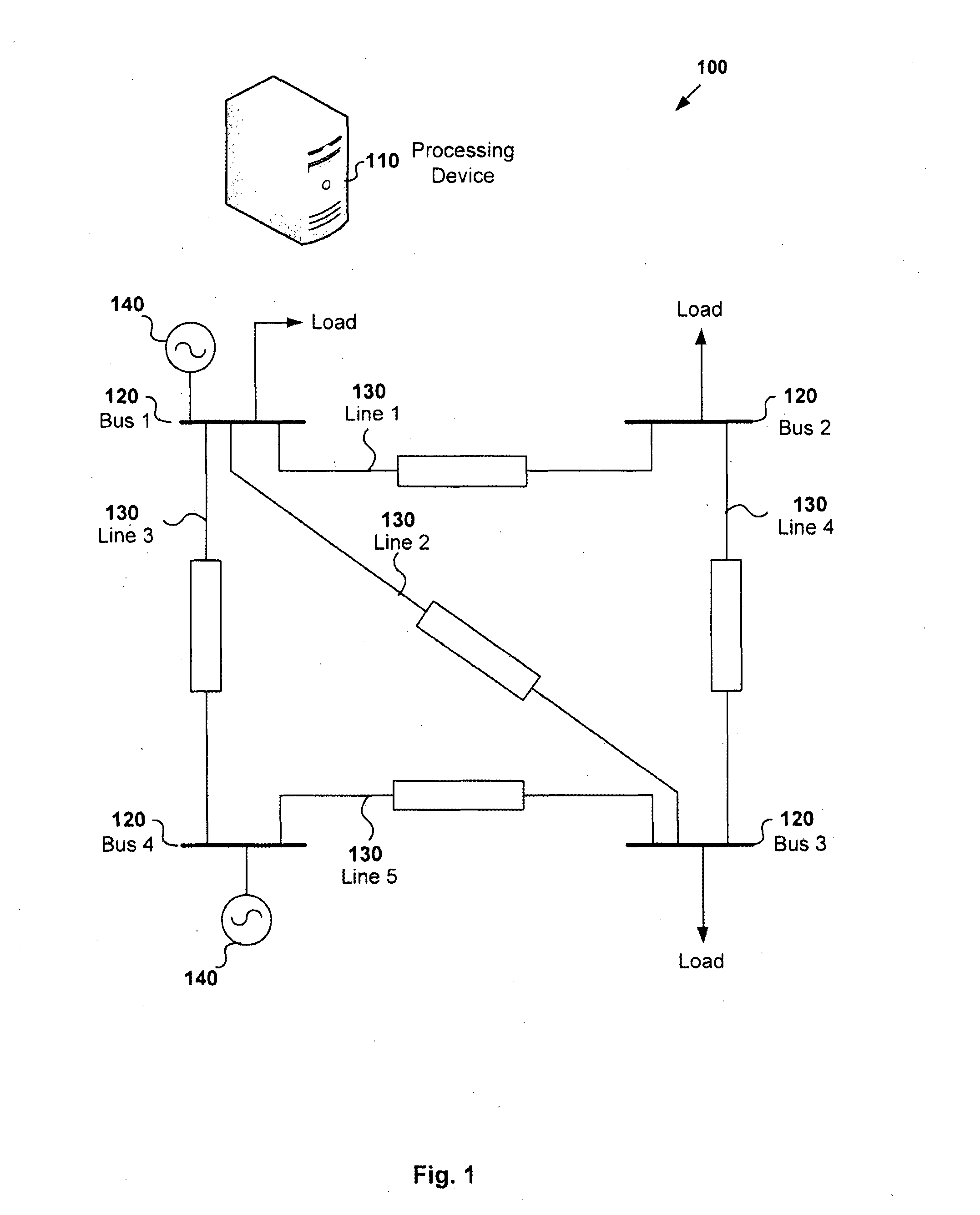
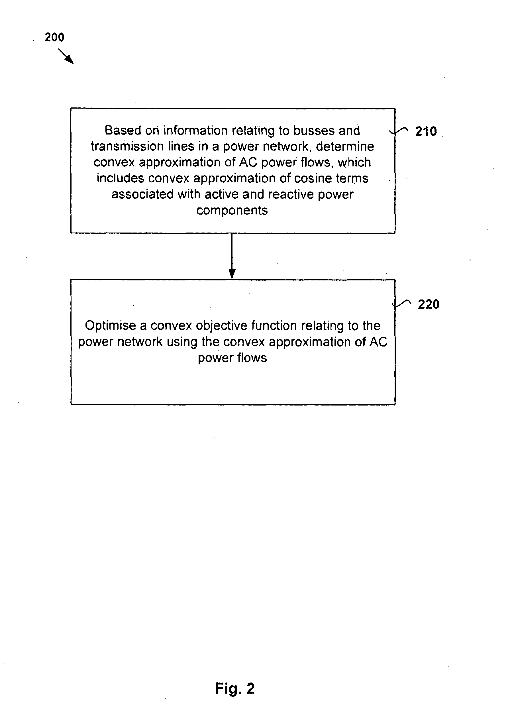
An alternating current (AC) power flow analysis in an electrical power network. Based on information relating to buses and transmission lines connecting the buses in the electrical power network, a convex approximation of AC power flows in the electrical power network is determined. The convex approximation of the AC power flows comprises convex approximation of nonlinear cosine terms associated with active power components and reactive power components of the AC power flows. A convex objective function associated with the electrical power network is optimised using the convex approximation of the AC power flows.

Description

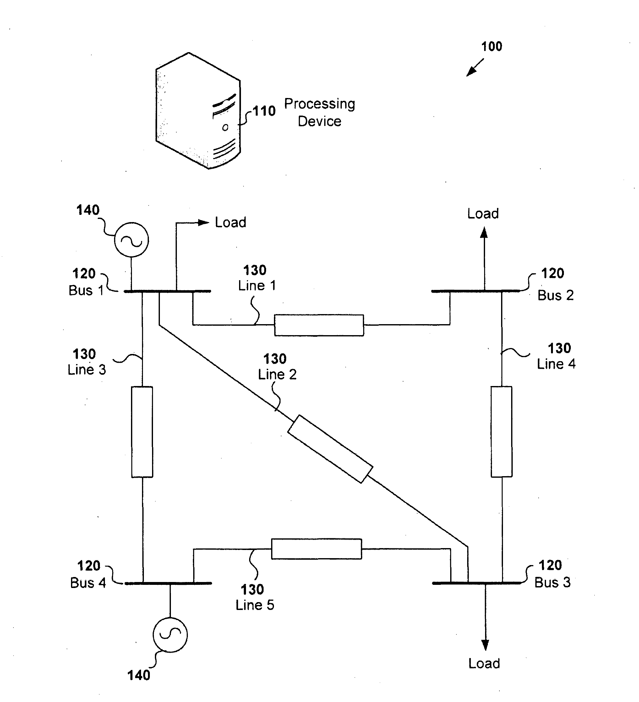
CROSS REFERENCE TO RELATED APPLICATION[0001]The present application claims priority from Australian Provisional Application No. 2012902118, the content of which is incorporated by reference.TECHNICAL FIELD[0002]This disclosure generally concerns electrical power networks, and more particularly, a computer-implemented method for AC power flow analysis in an electrical power network. This disclosure also concerns a computer system, a computer program and an electrical power network employing the method.BACKGROUND[0003]Optimization technology is ubiquitous in modern power systems and resulted in cost savings. However, the increasing role of demand response, the integration of renewable sources of energy, and the desire for more automation in fault detection and recovery pose new challenges for the planning and control of electrical power systems. Power grids now need to operate in more stochastic environments and under varying operating conditions, while still ensuring system reliabili...

Claims


Application Information

Patent Timeline
IPC IPC(8): G01R21/06H02J3/00
CPCH02J3/00G01R21/06G06Q50/06H02J2203/20Y02E40/70Y02E60/00Y04S10/50Y04S40/20Y04S20/222Y02B70/3225H02J3/007G06Q20/06
Inventor COFFRIN, CARLETONHIJAZI, HASSANVAN HENTENRYCK, PASCAL
Owner NAT ICT AUSTRALIA
Learn More