
Apparatus for tuning multi-band frame antenna

Active Publication Date: 2015-03-26
SONY CORP
View PDF6 Cites 67 Cited by
  • Summary
  • Abstract
  • Description
  • Claims
  • Application Information

AI Technical Summary

Benefits of technology

The patent describes a special antenna that can be used for multiple frequency bands. It consists of a conductive block and a metallic frame, with no gaps or discontinuities. The conductive block serves as the main ground and has electronic components mounted on its surface. The metallic frame surrounds the conductive block and has a small gap between it and the conductive block. The antenna feed is routed across this gap, and there are also connections made across the gap to connect the conductive block to the metallic frame. The technical effect is a multi-band frame antenna that can be used for LTE, MIMO, and other frequency bands.

Problems solved by technology

The conventional wideband antenna designs do not generally meet the strict requirements in hand-head user mode (a carrier / customer specified requirement) and in real human hand mode (reality usage).
A electronic device housing with a plastic frame painted with NCVM is very prone and vulnerable to color fading, cracks, and scratches.
The NCVM can cause serious antenna performance degradation if the NCVM process is not implemented properly, which has happened in many cases due to difficulties in NCVM machinery control, manufacturing process imperfections, and mishandling.
Also, the appearance of NCVM does not give a metallic feeling, and looks cheap.
Conventional antennas for smartphones and other portable devices do not generally react well in the presence of a continuous ring of surrounding metal, as the metal negatively affects the performance of these antennas.
As recognized by the present inventor, a problem with the antenna segments that surround the electronic device is that when a human's hands are placed on the smartphone, the human tissue serves as a circuit component that bridges the gap between segments and detunes the antenna, thus degrading performance.
Moreover, these devices are sensitive to human contact due to the several slots being in direct contact with the human hand during the browsing and voice mode and creating a hotspot being around the affected slot.

Method used


Image

  • Apparatus for tuning multi-band frame antenna
  • Apparatus for tuning multi-band frame antenna
  • Apparatus for tuning multi-band frame antenna

Examples


Embodiment Construction

[0046]In the drawings, like reference numerals designate identical or corresponding parts throughout the several views. Further, as used herein, the words “a,”“an” and the like generally carry a meaning of “one or more,” unless stated otherwise. The drawings are generally drawn to scale unless specified otherwise or illustrating schematic structures or flowcharts.

[0047]Furthermore, the terms “approximately,”“about,” and similar terms generally refer to ranges that include the identified value within a margin of 20%, 10%, or preferably 5%, and any values therebetween.

[0048]Aspects of the related disclosure are related to a optimizing the performance of a multi-band frame antenna. Throughout the disclosure, tuning of one or more antenna feeds is discussed. Within the disclosure, tuning can refer to any action that optimizes antenna performance or increases antenna efficiency, such as impedance matching, modifying an electrical length of an antenna, shifting a resonance frequency, remo...


PUM


Abstract

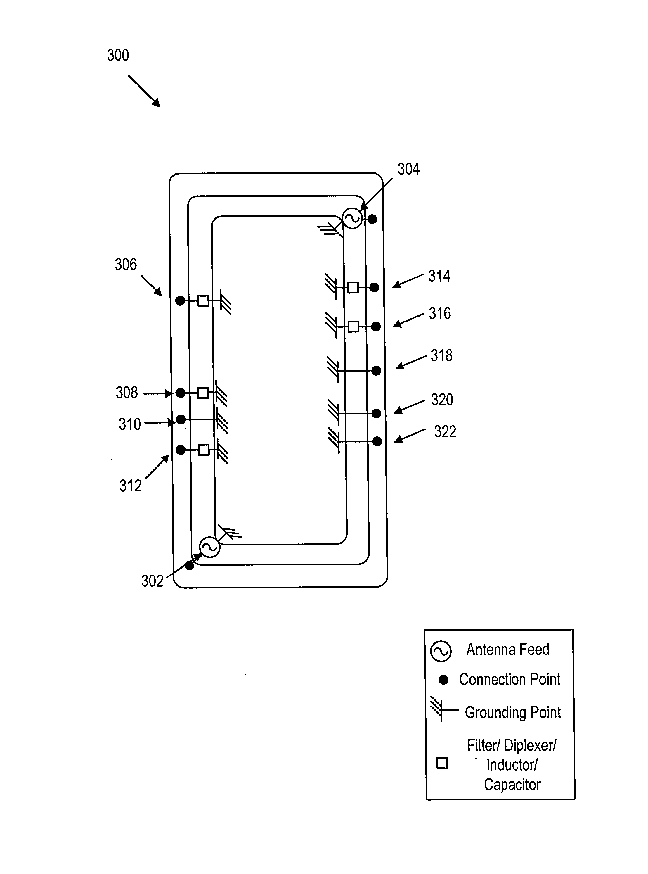
A multi-band frame antenna is used for LTE, MIMO, and other frequency bands. The frame antenna includes a conductive block and a metallic frame with no gaps or discontinuities. The conductive block functions as a system ground and has at least one electronic component mounted on the surface. The outer perimeter of the metallic frame surrounds the conductive block, and there is a gap between the metallic frame and the conductive block. One or more antenna feeds are routed across the gap, between the metallic frame and the conductive block. One or more connections can be made across the gap, and at least one electronic element connects the conductive block to the metallic frame.

Description

CROSS-REFERENCE TO RELATED PATENT APPLICATIONS[0001]The present application claims the benefit of the earlier filing date of U.S. provisional application 61 / 880,635 having common inventorship with the present application and filed in the U.S. Patent and Trademark Office on Sep. 20, 2013, the entire contents of which being incorporated herein by reference. In addition, the present application incorporates by reference the entire contents of U.S. patent application Ser. No. 13 / 962,539 having common inventorship with the present application and filed in the U.S. Patent and Trademark Office on Aug. 8, 2013.BACKGROUND[0002]1. Field of Disclosure[0003]This disclosure relates to a multi-band frame antenna, and more specifically, to a multi-band frame antenna to be used for multiple-input multiple-output (MIMO), Global System for Mobile Communications (GSM), General Packet Radio Service (GPRS), Enhanced Data-rates for Global Evolution (EDGE), Long Term Evolution (LTE) Time-Division Duplex (...

Claims


Application Information

Patent Timeline
IPC IPC(8): H01Q1/24H01Q5/00H01Q1/50
CPCH01Q1/243H01Q5/0062H01Q5/0041H01Q1/50H01Q3/247H01Q9/0464H01Q9/145H01Q5/328H01Q5/35H01Q5/378H01Q5/335
Inventor YONG, CHECK CHIN
Owner SONY CORP
Learn More