Method and apparatus for tracking transmission level of a home network signal in a broadcast signal receiving device

a technology of broadcast signal and transmission level, which is applied in the direction of broadcast system types, selective content distribution, television systems, etc., can solve the problems of significant difficulties in creating a suitable diplex or multiplex filter, system operation may be further complicated, and the filtering between these signals may not be sufficient to prevent interference to the reception of satellite signals

Inactive Publication Date: 2015-03-19
MAGNOLIA LICENSING LLC
View PDF2 Cites 4 Cited by
  • Summary
  • Abstract
  • Description
  • Claims
  • Application Information

AI Technical Summary

Problems solved by technology

However, a system receiving multiple signals from multiple services over a wide range of frequencies creates significant difficulties in creating a suitable diplex or multiplex filter that provides optimal performance for all services.
System operation may be further complicated by the inclusion of an interface to a wired home communication network, such as a Multimedia over Cable Alliance (MoCA) network.
In configurations that operate with both satellite broadcast and home communication signals, the filtering between these signals may not be sufficient enough to prevent interference to the reception of the satellite signals caused by transmission of the home network signal from the device.
Insufficient frequency spacing may not allow suitable filtering for attenuating transmitted home network signal.
As a result, signal energy from the transmitted home network signal may be present at the signal level detector and may affect the operation of the signal level detector, particularly at lower signal input levels for the satellite signal.
The additional signal energy may cause an incorrect gain setting for the satellite signal level and a degraded performance for satellite signal reception.
The problem may be further exacerbated by the type of gain control circuit that is used.

Method used

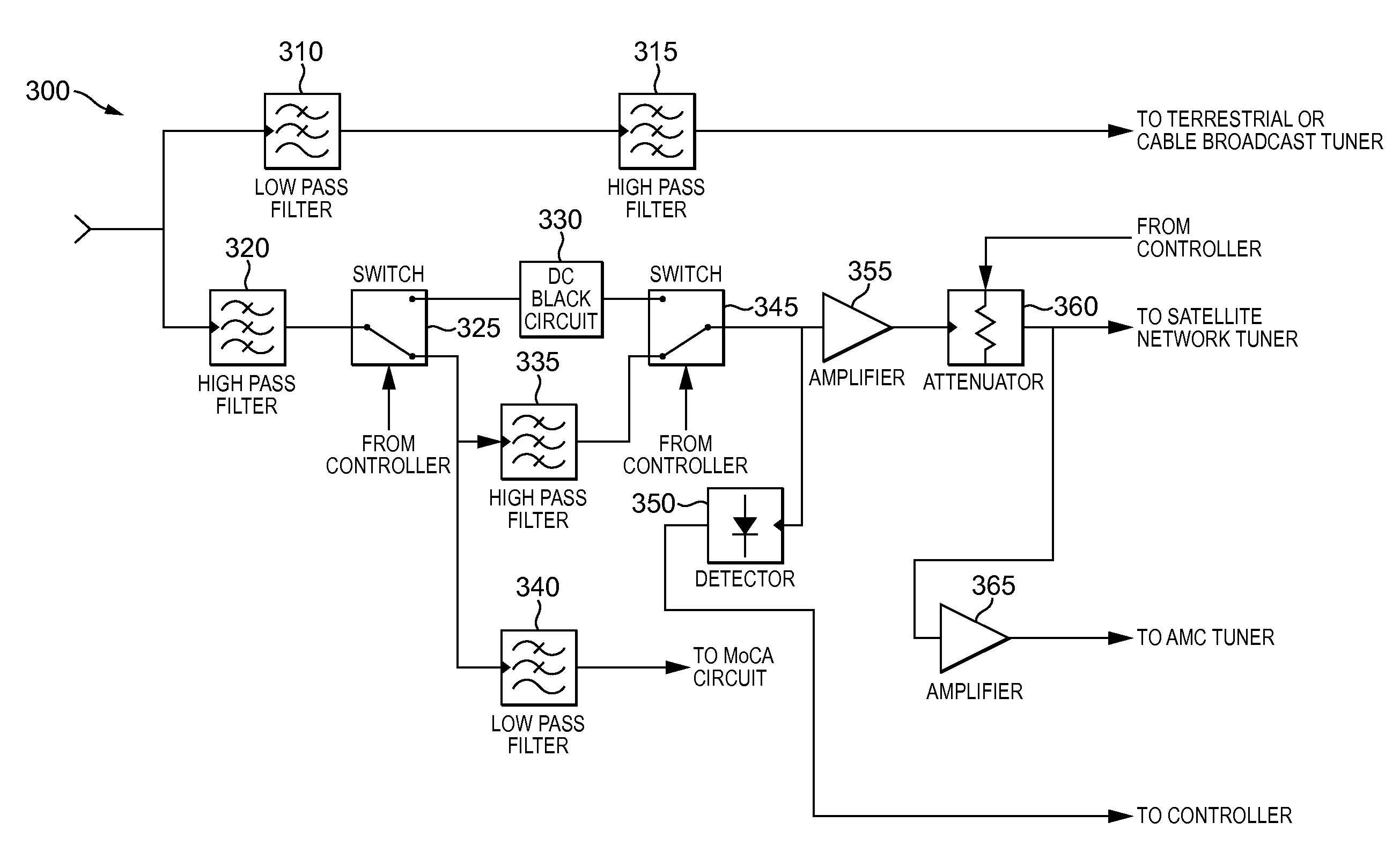
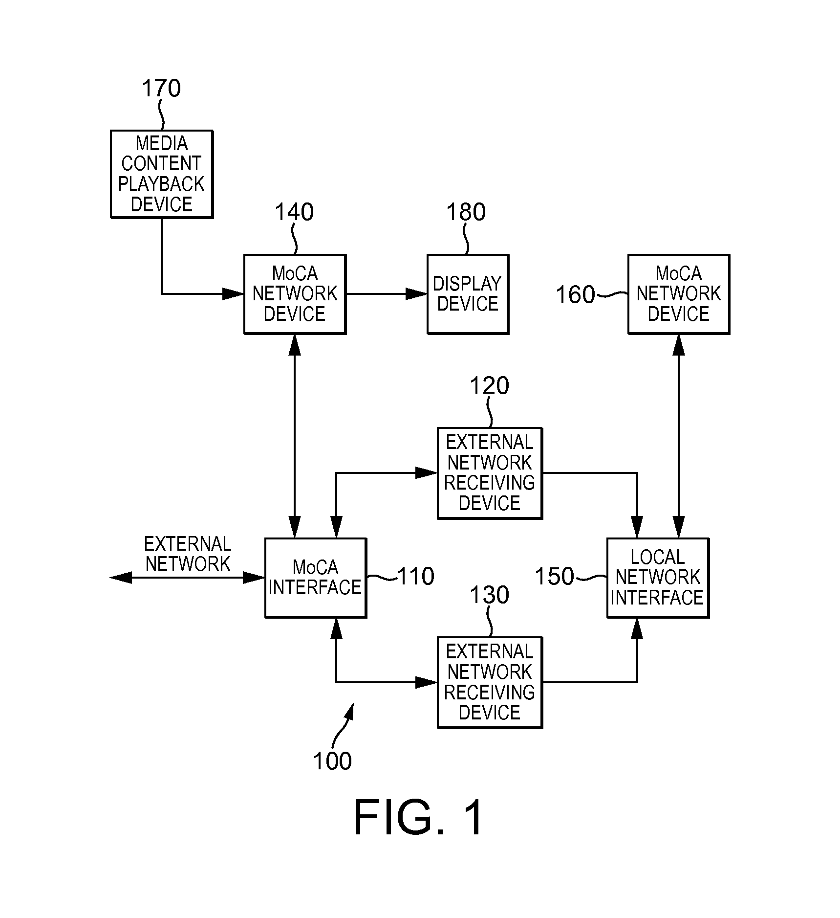
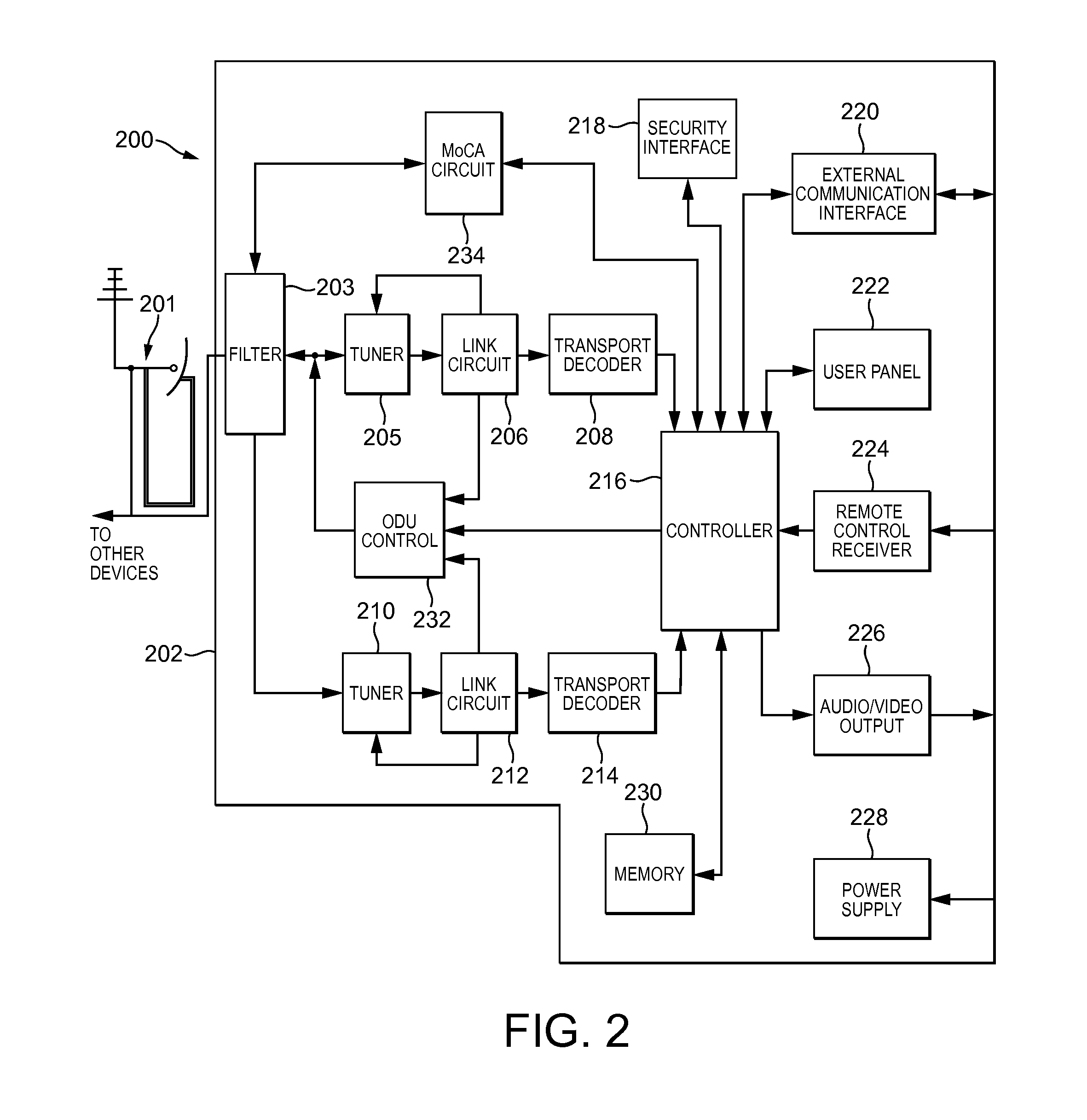

Image

  • Method and apparatus for tracking transmission level of a home network signal in a broadcast signal receiving device
  • Method and apparatus for tracking transmission level of a home network signal in a broadcast signal receiving device
  • Method and apparatus for tracking transmission level of a home network signal in a broadcast signal receiving device

Examples


Embodiment Construction

[0016]It should be understood that the elements shown in the figures may be implemented in various forms of hardware, software or combinations thereof. Preferably, these elements are implemented in a combination of hardware and software on one or more appropriately programmed general-purpose devices, which may include a processor, memory and input / output interfaces. Herein, the phrase “coupled” is defined to mean directly connected to or indirectly connected with through one or more intermediate components. Such intermediate components may include both hardware and software based components.

[0017]The present description illustrates the principles of the present disclosure. It will thus be appreciated that those skilled in the art will be able to devise various arrangements that, although not explicitly described or shown herein, embody the principles of the disclosure and are included within its scope.

[0018]All examples and conditional language recited herein are intended for educat...


PUM


Abstract

A method and apparatus for tracking the transmission power level of a home network transmission signal based on the signal level of a received broadcast signal is described. The method includes transmitting a signal at a first transmitted level used for communicating in a home network, detecting a signal level for the transmitted signal in a circuit used for receiving a broadcast signal, determining if a gain setting value for the signal level changes, and adjusting the transmitted signal level for the transmitted signal based on the determination. The apparatus includes a network circuit that transmits a signal at a first transmitted signal level, a detector that detects the transmitted signal in a circuit for receiving a broadcast signal, and a controller that determines if a signal level setting value for the signal level changes and adjusts the transmitted signal level based on the determination.

Description

CROSS REFERENCE TO RELATED APPLICATION[0001]This application claims priority from U.S. Provisional Application No. 61 / 879,830 filed Sep. 19, 2013.TECHNICAL FIELD OF THE INVENTION[0002]The present disclosure generally relates to devices that receive broadcast signals and also operate in home networks. More specifically, the present disclosure relates to a method and apparatus for tracking transmission level of a home network signal in a broadcast signal receiving device.BACKGROUND OF THE INVENTION[0003]This section is intended to introduce the reader to various aspects of art, which may be related to the present embodiments that are described below. This discussion is believed to be helpful in providing the reader with background information to facilitate a better understanding of the various aspects of the present disclosure. Accordingly, it should be understood that these statements are to be read in this light.[0004]Many home entertainment devices not only include the capability t...

Claims


Application Information

Patent Timeline
Patent Type & Authority Applications(United States)
IPC IPC(8): H04N21/61H04N21/436H04N7/20H04H40/90
CPCH04N21/615H04H40/90H04N21/436H04N7/20H04H2201/60H04N21/6143H04H2201/16H04H2201/14H04N21/6118H04N7/104H04N7/106H04N17/004
Inventor XIU, LINCHENGPERRIN, JEFFRY HOLSCLAW
Owner MAGNOLIA LICENSING LLC
Why Eureka
Try Eureka