Image forming apparatus
a technology of forming apparatus and forming locus, which is applied in the direction of electrographic process apparatus, instruments, optics, etc., can solve the problems of difficult to ensure a mounting locus, and achieve the effects of shortening the fpot, improving usability, and reducing the size of the main assembly of the apparatus
- Summary
- Abstract
- Description
- Claims
- Application Information
AI Technical Summary
Benefits of technology
Problems solved by technology
Method used
Image
Examples
reference example 1
General Structure of Image Forming Apparatus
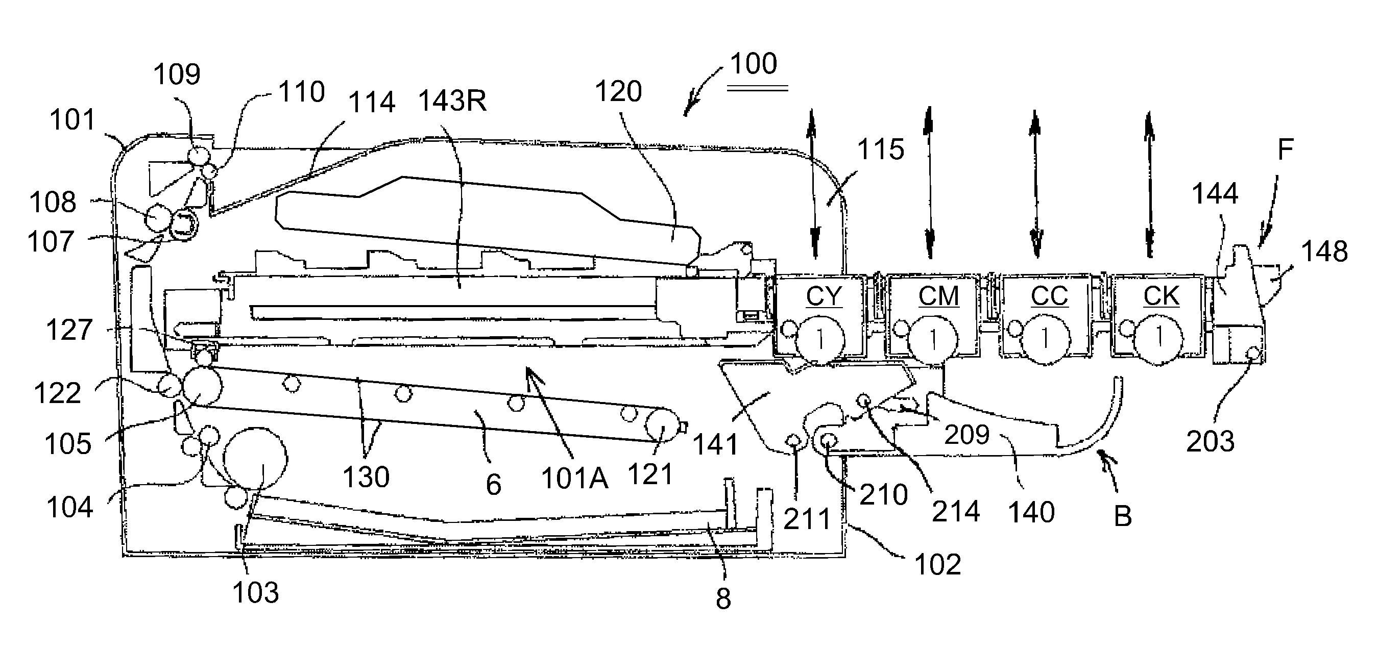
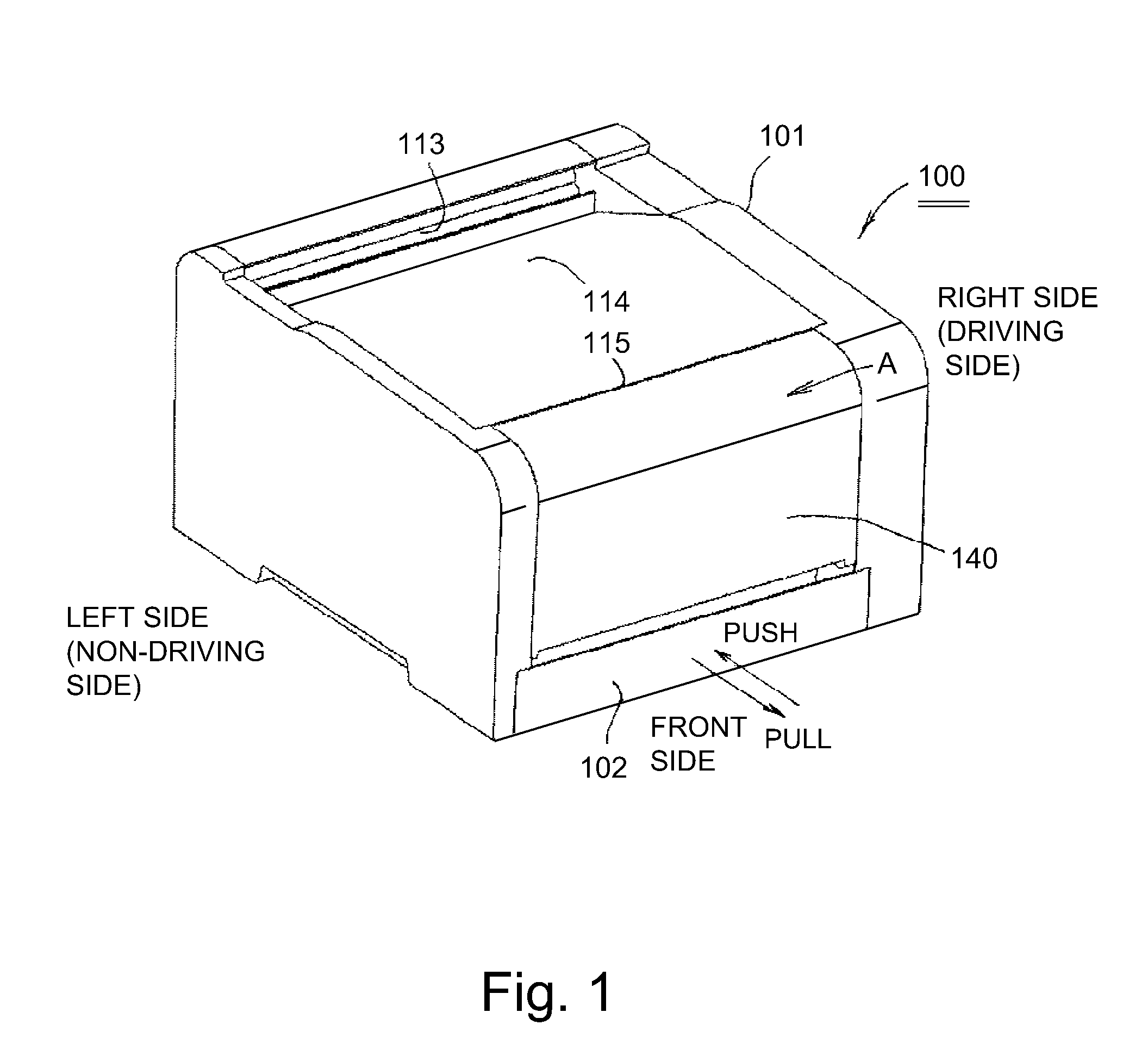
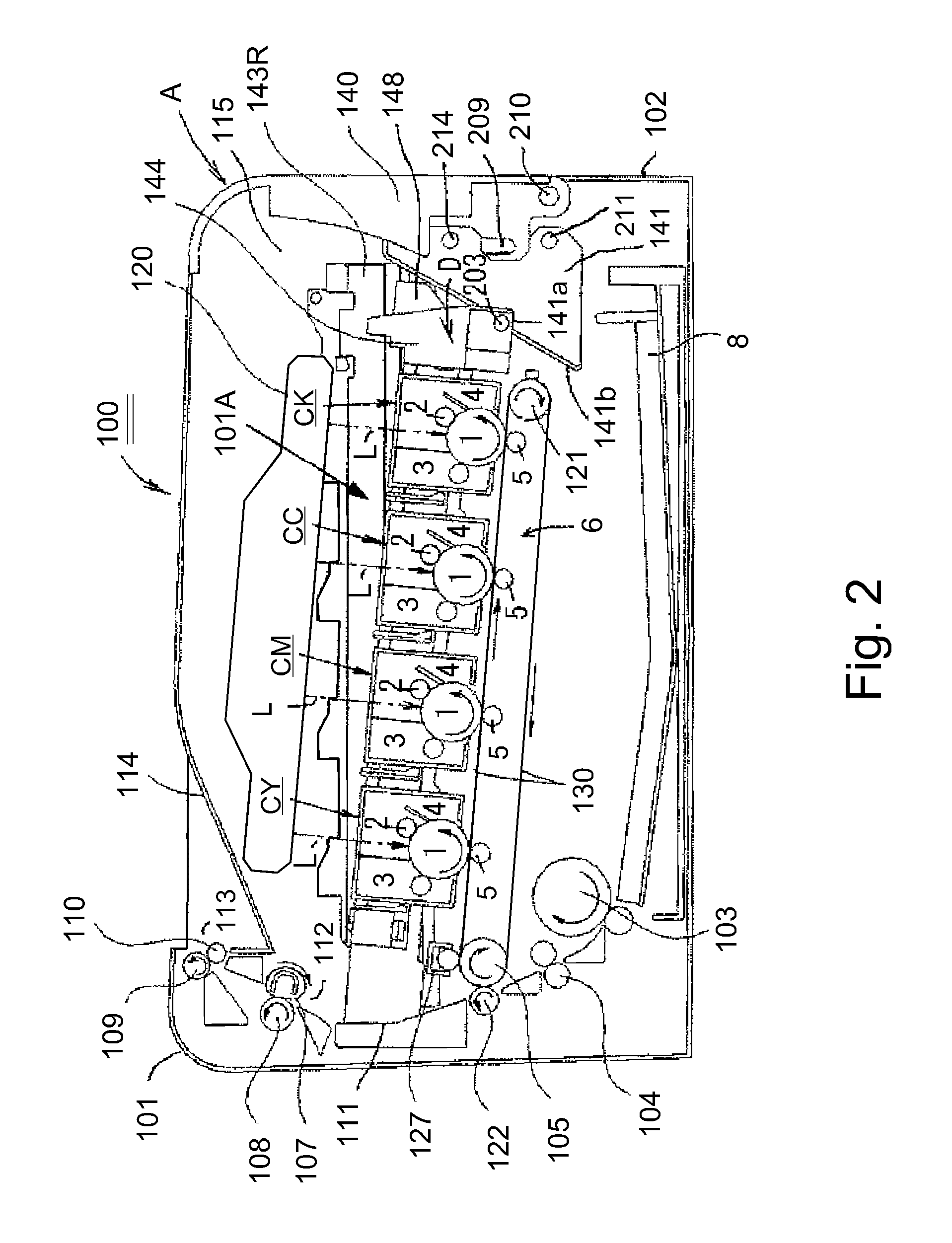
[0048]FIG. 1 is a perspective view of an outer appearance of an image forming apparatus 100 in this embodiment, and FIG. 2 is a schematic longitudinal left side view of the image forming apparatus 100. The image forming apparatus 100 is a four color-based full-color laser printer using an electrophotographic process, to which four integral-type process cartridges C (CY, CM, CC, CK) as a plurality of cartridges contributing to image formation. That is, the image forming apparatus 100 is capable of effecting full-color or monochromatic image formation on a sheet-like recording material 8 as a recording medium on the basis of an electrical image signal inputted from an external host device (not shown) such as a personal computer or an image reader into a control circuit portion (not shown).
[0049]In the following description, with respect to the image forming apparatus 100, a front (surface) side means the side where a cartridge door 140 as an...
reference example 2
[0120]FIGS. 13 to 19 are illustrations of an image forming apparatus in Reference Example 2. In Reference Example 2, constituent members or portions similar to those of the image forming apparatus 100 in Reference Example 1 described above are represented by the same reference numerals or symbols and will be omitted from redundant description. Further, indication of the reference numerals or symbols in the drawings in partly omitted.
[0121]FIG. 13 is a schematic longitudinal left side view of an image forming apparatus 100 in Reference Example 2. The first to fourth cartridges CY, CM, CC and CK are arranged, in the listed order from the rear side toward the front side, obliquely toward an upper front side with respect to the horizontal direction, and are positionally fixed and mounted at predetermined mounting positions (image formation positions). At this mounting position, each cartridge C is capable of performing an image forming operation.
[0122]Incidentally, in the image forming ...
embodiment 1
General Structure of Image Forming Apparatus
[0140]FIGS. 20 to 26 are illustrations of an image forming apparatus 100 in Embodiment 1. In this embodiment, constituent members or portions similar to those of the image forming apparatus 100 in Reference Examples 1 and 2 described above are represented by the same reference numerals or symbols and will be omitted from redundant description. Further, indication of the reference numerals or symbols in the drawings in partly omitted.
[0141]FIG. 20 is a schematic longitudinal left side view of the image forming apparatus 100 in this embodiment in a state in which the door 140 is closed. The clocked state of the door 140 is stably held by the locking mechanism (not shown). The image forming apparatus 100 in this embodiment is basically a four color-based full-color laser printer, using an electrophotographic process, to which four cartridges C (CY, CM, CC, CK) are detachably mountable similarly as in the image forming apparatuses 100 in Refer...
PUM
 Abstract
Description
Claims
Application Information
 - R&D
- Intellectual Property
- Life Sciences
- Materials
- Tech Scout
- Unparalleled Data Quality
- Higher Quality Content
- 60% Fewer Hallucinations
Browse by: Latest US Patents, China's latest patents, Technical Efficacy Thesaurus, Application Domain, Technology Topic, Popular Technical Reports.
© 2025 PatSnap. All rights reserved.Legal|Privacy policy|Modern Slavery Act Transparency Statement|Sitemap|About US| Contact US: help@patsnap.com


