
Electromagnetic powered sputum excretion system

Inactive Publication Date: 2015-02-19
BOYU MEDICAL ELECTRONICS CHANGSHULTD
View PDF10 Cites 7 Cited by
  • Summary
  • Abstract
  • Description
  • Claims
  • Application Information

AI Technical Summary

Benefits of technology

The present invention is a sputum excretion system that uses an electromagnet to create a vibrating airflow to help a patient excrete sputum. The system is controlled by an electromagnetic powered control unit that can select specific sputum excretion plans or control the start and stop times of the system. The device is easy to operate and low in cost, making it useful for a range of applications. The technical effects of the invention include quick and stable operation, low energy consumption, and the ability to assist patients with sputum excretion.

Problems solved by technology

The chest physical therapy comprises manual knocking on the back for sputum excretion, in vitro vibration machine for sputum excretion, but all of these suffer from many problems.
However, new problems are introduced as follow.
Firstly, the fixed two-point anterior chest wall pulse can not beat the side and back of the thorax, and the effect of sputum excretion is poor for some patients.
Secondly, once the treatment parameters have been set, the therapeutic procedure is performed in light of the standards completely, and is not interrupted even if it has induced the patient to cough, which may lead to risks like continuous coughing for a long time, consuming a lot of physical strength, and hyperventilation.
Besides, the air pressure compensator 21 is also realized by an electric motor, so that the whole system is slow in response and consumes significant electricity.

Method used


Image

  • Electromagnetic powered sputum excretion system
  • Electromagnetic powered sputum excretion system
  • Electromagnetic powered sputum excretion system

Examples


Embodiment Construction

[0048]In order to make objects, solutions, and advantages of embodiments of the present invention more clear, the technical solutions in embodiments the present invention will be described hereinafter in a clear and comprehensive manner by referring to drawings of embodiments of the present invention. It is obvious that the described embodiments are only some embodiments, instead of all embodiments, of the present invention. Embodiments, which will be achieved by the ordinary skilled in the art by starting from embodiments of the present invention without inventive work, fall within the protection scope of the present invention.

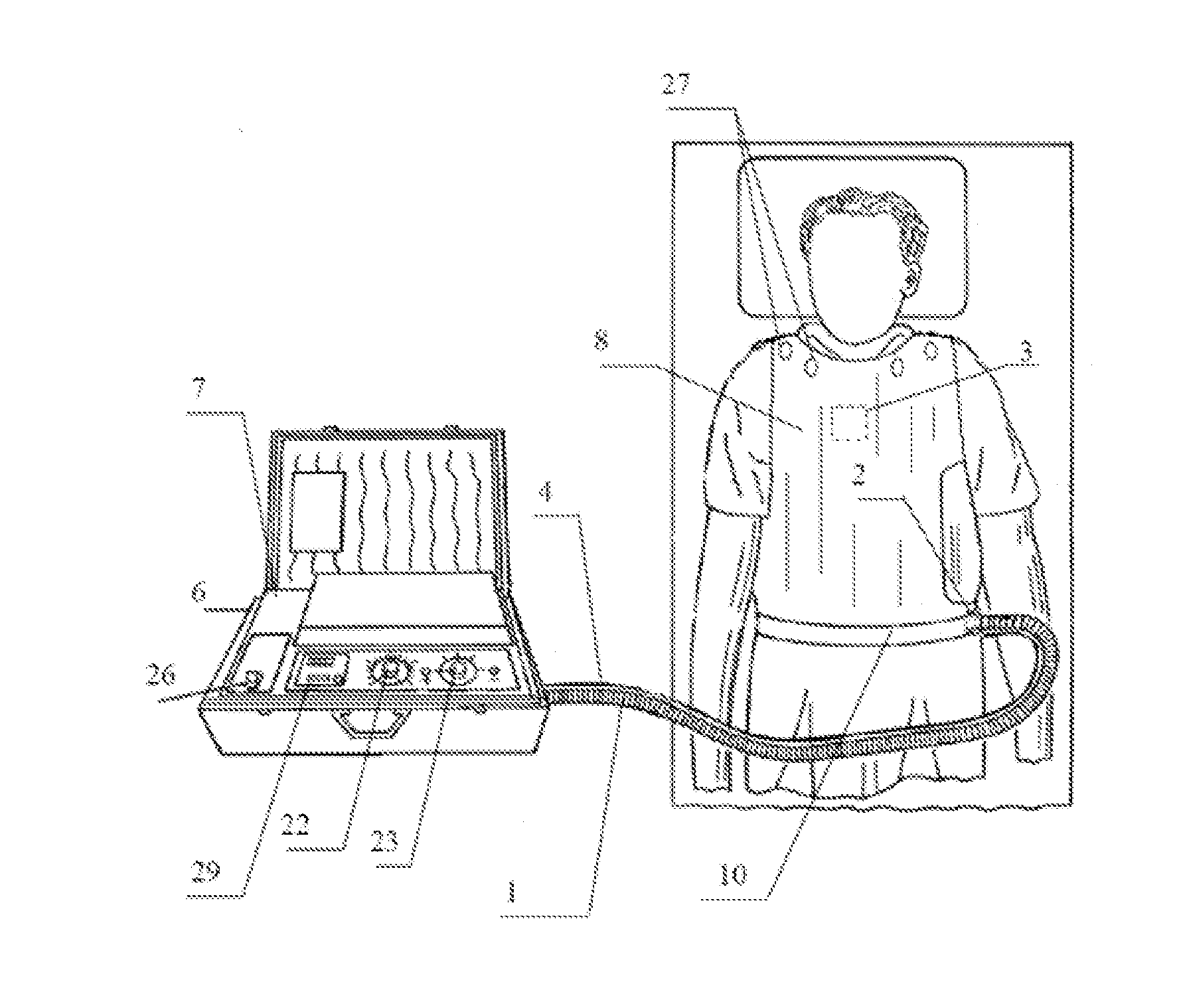
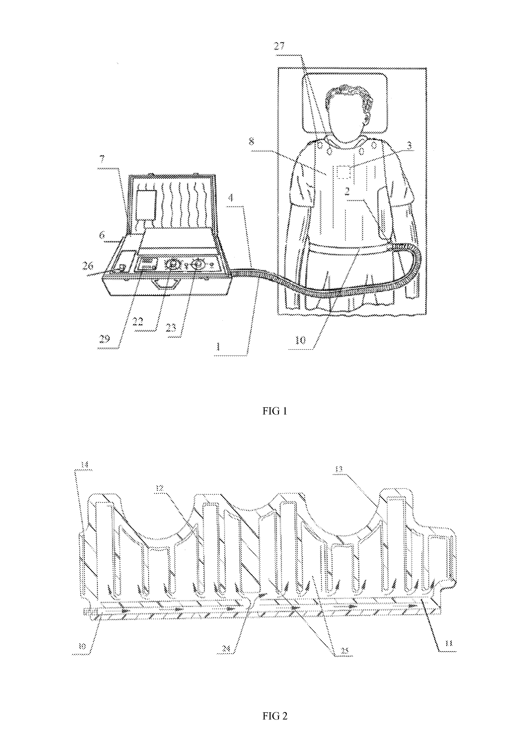
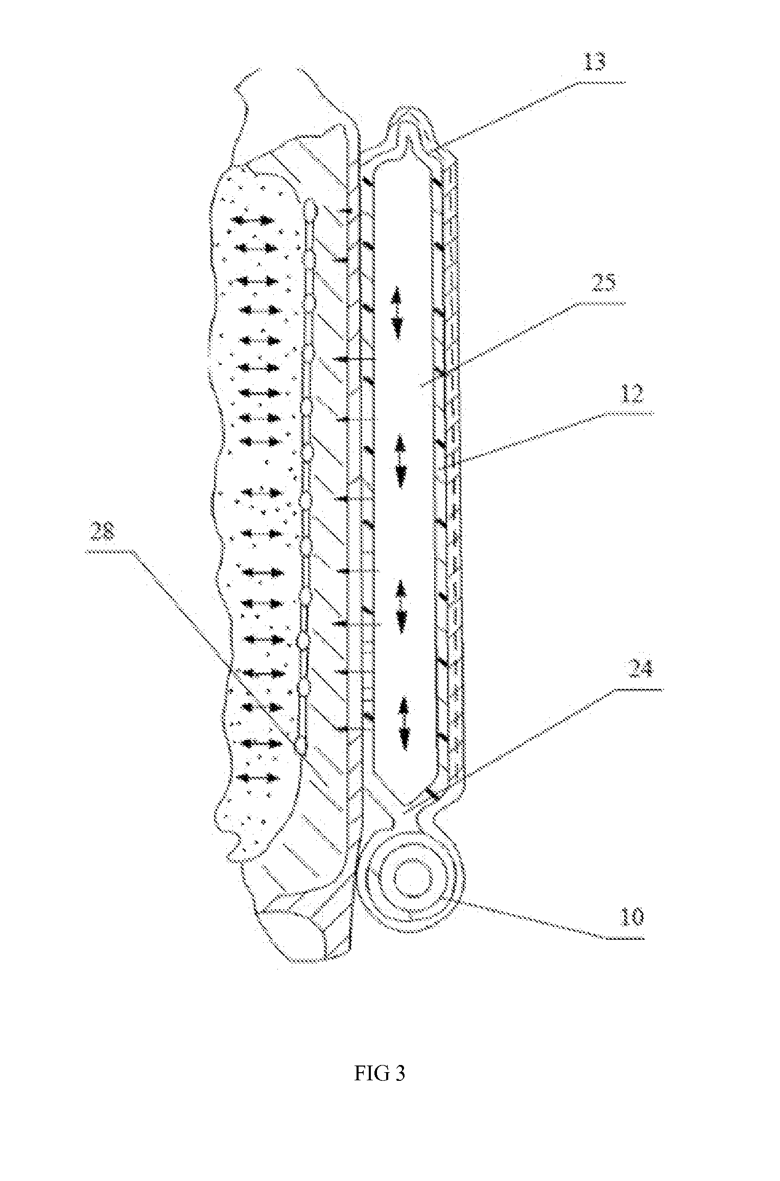
[0049]As shown in FIGS. 5-7, an electromagnetic powered sputum excretion device comprises a coughing sensor, a frequency input end, an air pressure input end, an electric-controlled switch, a timing input end, a pressure vest 80, an air vibration device 90, and a fan 70. The air vibration device 90 comprises a stainless steel belt II 903, iron clappers 904, a...


PUM


Abstract

An electromagnetic powered sputum excretion system comprises a coughing sensor, a frequency input end, an air pressure input end, an electric-controlled switch, a timing input end, a pressure vest (80), an air vibration device (90), and a fan (70). The air is extruded by attracting iron clappers (904) with an electromagnet (906) to generate a vibrating airflow, and the chest of a patient is vibrated by the action on the chest of the patient through the pressure vest (80), thereby the sputum excretion system assists the patient to excrete sputum. Since the control via the electromagnet (906) is characterized by promptness, stability, low energy consumption and the like, the sputum excretion system, which utilizes the electromagnet (906) as a power to generate the vibrating airflow, has above characteristics as well. The present sputum excretion system further has the advantages of simple operation and low cost.

Description

CROSS-REFERENCE TO RELATED APPLICATION[0001]This application is the U.S. national phase of International Application No. PCT / CN2012 / 075799, filed on May 21, 2012, which claims benefit of Chinese application 201210086533.7, flied Mar. 28, 2012, Chinese application 201220123170.5, flied Mar. 28, 2012, Chinese application 201210086464.X, flied Mar. 28, 2012, Chinese application 201220123168.8, flied Mar. 28, 2012, Chinese application 201210086463.5, flied Mar. 28, 2012 and Chinese application 201220123167.3, flied Mar. 28, 2012. The entire contents of which is hereby incorporated by reference.BACKGROUND OF THE INVENTION[0002]1. Field of the Invention[0003]The present invention relates to an electromagnetic powered sputum excretion system.[0004]2. Background of the Invention[0005]Chest physical therapy has a long history of clinical applications. It is very effective, and is among the standard of medical methods for improving airway mucus cleanup in various countries. The chest physical...

Claims


Application Information

Patent Timeline
IPC IPC(8): A61H23/02A61H9/00A61H23/04A61H1/00
CPCA61H23/02A61H1/00A61H9/0071A61H2031/025A61H2205/084A61H2201/5007A61H2201/5058A61H23/04A61H9/0078A61H2201/1619A61H2201/165A61H2201/5005A61H2201/5035A61H2201/5038A61H2201/5043
Inventor ZHOU, ZHENGHUIZHONG, ZHIHAN, SHAODANZHAO, YUXUYAN, JINCHAO
Owner BOYU MEDICAL ELECTRONICS CHANGSHULTD
Learn More