
Flying disc

a technology of flying discs and discs, which is applied in the field of flying discs, can solve the problems of discs that have a less than optimal ability to glide long distances, and achieve the effect of convenient disc throwing and easy grasping

Inactive Publication Date: 2015-02-05
LINDBERG JONAS
View PDF1 Cites 13 Cited by
  • Summary
  • Abstract
  • Description
  • Claims
  • Application Information

AI Technical Summary

Benefits of technology

The technical effect of this patent is that the face of the outermost rim of the disc is positioned parallel to the disc's center axis, which makes it easy to hold and throw the disc.

Problems solved by technology

A wide outer rim is however ill suited for grasping the disc, and the disc has a less than optimal ability to glide long distances.

Method used


Image

  • Flying disc
  • Flying disc
  • Flying disc

Examples


Embodiment Construction

[0014]The invention refers to a disc like object that is intended to the thrown into the air and used in a way similar to how a golf disc or Frisbee is used. The flying disc may be embodied in many different ways and still lie within the protective scope of the invention, but it is here exemplified by one embodiment only.

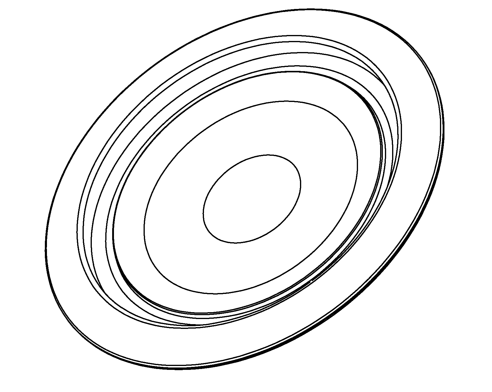
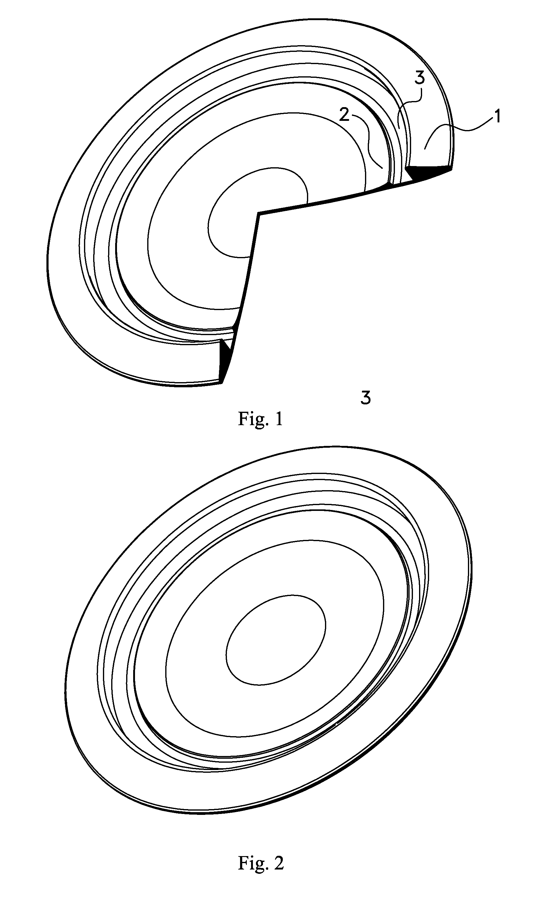
[0015]FIG. 1 shows the flying disc in partial cross section as seen at an angle from below, that is the figure illustrates the surfaces that while in use faces downwards. One quarter of the disc has been cut out in order to make understanding the figure easier, but in reality the disc of course looks like how it is depicted in FIG. 2.

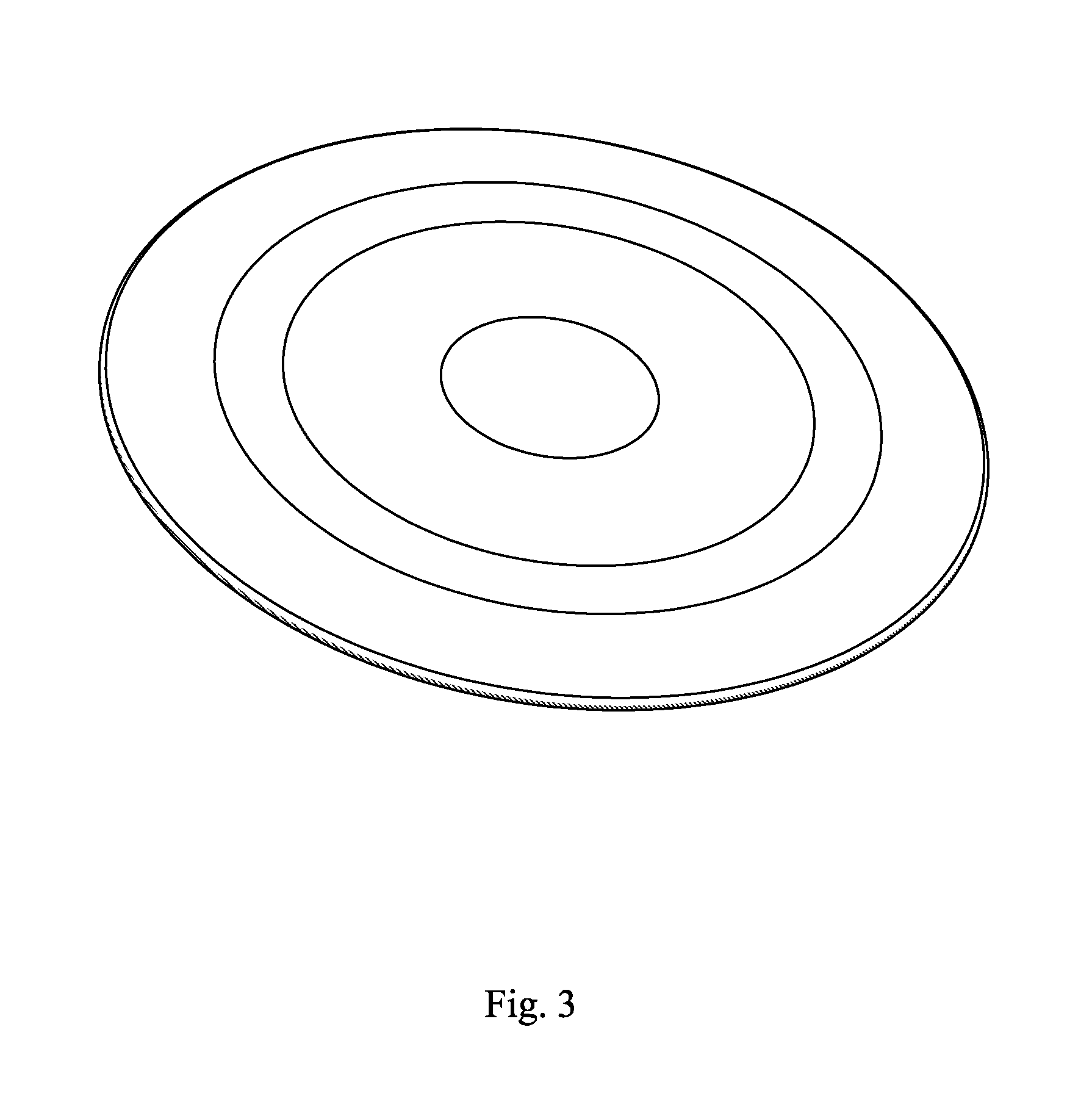
[0016]As seen from below, the disc is a circularly symmetrical object with an outermost, circular rim 1. The lower side of the disc has a number of concentrically arranged design features that will be described in greater detail in conjunction with FIGS. 4-5. The outermost rim 1 is the design feature that extend the furthermost from the...


PUM


Abstract

The invention relates to a flying disc constituted as a disc with a first and a second side. The second side has a central portion that is concave and the central portion is surrounded by an innermost rim (2) and an outermost rim (1) extending to the disc's periphery. The innermost rim (2) is separated from the outermost rim (1) by a circularly symmetrical depression (3). This depression gives the disc superior aero dynamical properties, allowing it to glide further in the air than corresponding prior art discs.In one embodiment, the face of the outermost rim (1) nearest the centre of the disc extends essentially in parallel to the centre axis of the disc. This makes it particularly easy to grasp the disc and facilitates throwing the disc.In another embodiment, the concave central portion of the second side extends along a virtual concave surface to the innermost rim, where the virtual concave surface further extends essentially to the part of the outer rim that extend the furthest from the first side of the disc. This further optimizes the aero dynamical properties of the disc.Typically, the outermost rim (1) has a face on the second side of the disc, which is concave, and the first side of the disc is convex.

Description

[0001]The present invention relates to a flying disc according to the introductory portion of the independent claim.BACKGROUND OF THE INVENTION[0002]Flying discs intended for sports of types similar to those call golf discs of Frisbees are known in the art. One example of such a disc is disclosed by EP2407223, showing a disc with a convex upper side and a concave lower side extending to a solid outer rim. The outer rim constitutes most of the mass of the disc and gives the disc an enhanced ability to spin while gliding through the air. A wide outer rim is however ill suited for grasping the disc, and the disc has a less than optimal ability to glide long distances.[0003]An object of the invention is therefore to provide a flying disc with improved aero dynamical properties than with prior art discs, allowing it to fly longer distances than prior art discs.[0004]These and other objects are attained by a flying disc according to the characterising portion of the independent claim.SUMM...

Claims


Application Information

Patent Timeline
Patent Type & Authority Applications(United States)
IPC IPC(8): A63H33/18
CPCA63H33/18
Inventor LINDBERG, JONAS
Owner LINDBERG JONAS
Learn More