Railroad spike for attaching a metal rail to a wooden tie

Inactive Publication Date: 2015-02-05
HEXAGON INT
View PDF3 Cites 6 Cited by
  • Summary
  • Abstract
  • Description
  • Claims
  • Application Information

AI Technical Summary

Benefits of technology

The patent text describes a new type of railway spike that connects metal and wood members. The spike has a head with a flange and a standoff, and an intermediate section with a holding ring that engages the wood member. The spike also has a threaded shank that engages the wood member. The patent also describes a fastener with an improved holding ring that prevents the fastener from backing out of the wood member. Overall, these new solutions improve the stability and durability of the connection between metal and wood members in railways.

Problems solved by technology

However, if they have the proper thread pitch, they can either be screwed in or pounded in.
The known screw spikes often work loose from the tie after being in service for a period of time.
Attempts to secure or anchor the spike by providing the shank of the spike with burrs, barbs, serrations or other rough features adapted to engage with the wooden tie into which it is driven have generally proven unsatisfactory.
One problem with such spikes is that it is difficult to drive them into the tie manually, or even using automated impact spike driving methods.
Moreover, the spike may, during installation, chew or tear the wood fibers of the tie, thereby causing damage to the tie.
In addition, if the spikes have been in service for a length of time, they will have a tendency to “work”, i.e. move, in the hole established in the tie by the shank of the spike.
This enlarges the hole in the tie surrounding the shank and damages the adjacent wood fibers, causing the spike to loosen in the tie over time.
The enlarged hole is also disadvantageous because it permits water and various harmful chemicals to enter the hole in the wood, thereby further weakening the joint between the spike and the surrounding wood.
Furthermore, removal of the spike usually causes additional damage to the tie.
However, such spikes are difficult to install and generally require a predrilled hole in the tie to facilitate installation using rotary spike driving methods.
However, such spikes are difficult to install using automated equipment and can generally be used only in conjunction with a particular tie plate design.
Moreover, such spikes are extremely difficult to remove once locked into engagement with the tie plate that they are adapted to mate with.

Method used


Image

  • Railroad spike for attaching a metal rail to a wooden tie
  • Railroad spike for attaching a metal rail to a wooden tie
  • Railroad spike for attaching a metal rail to a wooden tie

Examples


Embodiment Construction

[0020]FIG. 1 illustrates a typical railway installation. More particularly, illustrated is a metal rail 18 which is fastened to a wood tie 9 using a fastener or spike 1 according to one embodiment of the present disclosure. A metal tie plate 12, including an elastic fastener 16, engages with a flange 14 of the metal rail 18. A plurality of such spikes 1 is inserted, each into a respective one of a plurality of apertures extending through the tie plate 12 in order to secure the tie plate 12, and hence the rail 18, to the tie 9.

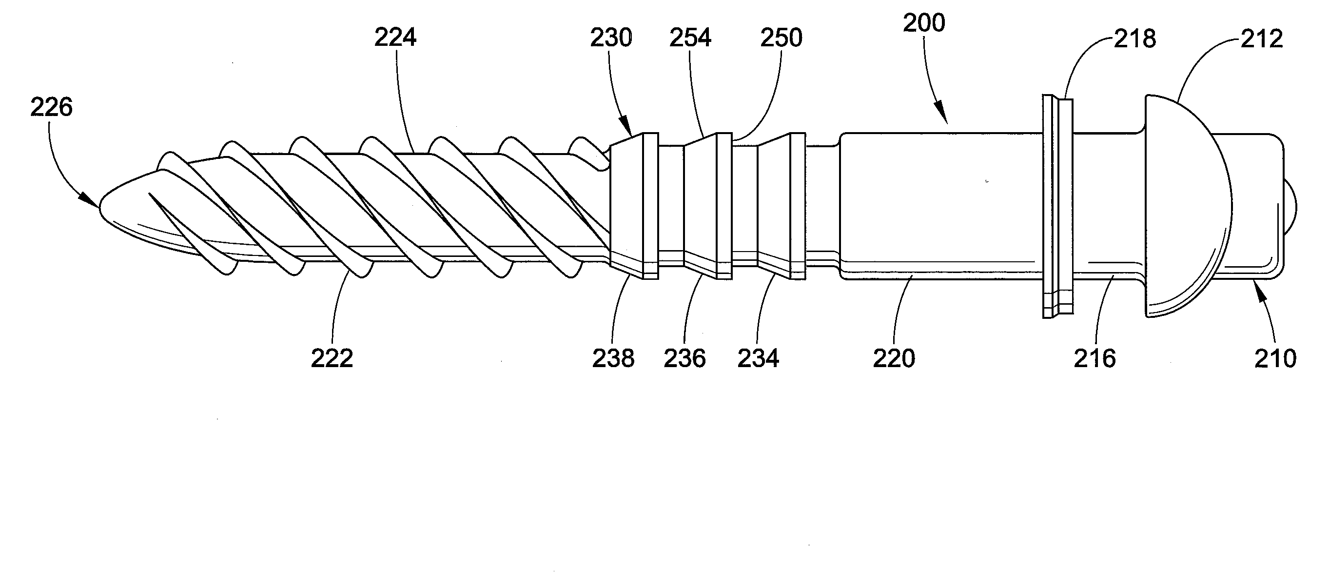
[0021]With reference now to FIG. 2, the spike 1 includes a head 10 comprising a first annular flange 11 and a standoff 15 extending axially away from the flange 11 in a direction opposite to a tool grip defined on the head 10. In this design, the standoff is generally cylindrical and does not include any protrusions, such as burrs, barbs, serrations, flutes or similar rough features. Extending axially from the standoff 15 is a shank 5. Disposed between the shan...


PUM

PropertyMeasurementUnit
Angleaaaaaaaaaa
Diameteraaaaaaaaaa

Abstract

A railway spike for connecting an associated metal member with an associated wood member includes a head including an annular flange and a standoff extending axially from the flange. An intermediate section extends axially from the standoff. At least one holding ring is disposed on the intermediate section. The at least one holding ring extends radially away from the intermediate section and is adapted to engage the associated wood member. A shank extends axially from the standoff. The shank includes a thread which is adapted to engage the associated wood member.

Description

[0001]This application claims the benefit of U.S. Provisional Application Ser. No. 61 / 862,247, filed on Aug. 5, 2013, and the benefit of U.S. Provisional Application Ser. No. 61 / 913,017, filed on Dec. 6, 2013. The subject matter of each of these applications is incorporated herein in its entirety.[0002]This disclosure relates to fasteners for securing a metal member to a wood member. More particularly, it relates to an improved railroad spike for attaching a metal rail to a wooden tie.BACKGROUND[0003]It is common in constructing railway tracks to provide rails supported on cross ties which are formed of wood. The rails themselves are commonly made of a metal, such as steel. The rails are generally provided with mounting flanges which are adapted to rest on metallic bearing plates. These are commonly referred to as tie plates. The tie plates, in turn, rest on wooden ties. Spikes are employed for securing the tie plates, and hence the rails, to the ties. Generally, a spike is inserted...

Claims


Application Information

Patent Timeline
IPC IPC(8): E01B9/06F16B25/00
CPCF16B25/0015E01B9/06
Inventor JACKSON, PETER M.
Owner HEXAGON INT
Why Eureka
Try Eureka