
Hyperdexterous surgical system

a surgical system and hyperdexter technology, applied in the field of surgical systems and methods, can solve the problems of robotic tools, not being well-suited for other surgical tasks, and the motion of the distal end of the tool relative to the proximal end of the tool may not be natural,

Inactive Publication Date: 2015-01-22
SRI INTERNATIONAL
View PDF7 Cites 822 Cited by
  • Summary
  • Abstract
  • Description
  • Claims
  • Application Information

AI Technical Summary

Benefits of technology

The hyperdexterous surgical system described in this patent provides a small and flexible surgical system that can be mounted in various ways and used with both robotic and manual tools. It allows surgeons to move around during surgery and access the patient's body from multiple angles. It also provides additional information to make the use of the surgical tools more natural. Additionally, the system allows for the repositioning of the surgeon and maximizes the workspace inside the patient's body.

Problems solved by technology

The resulting motion of the distal end of the tool relative to the motion of the proximal end of the tool may not be natural, requiring the surgeon to practice the technique.
The robotic tool is configured to do certain surgical tasks well, but is not well-suited for other surgical tasks.
This mode of operation is limiting for large motions or motions where it is more natural to move with respect to a frame of reference outside the body of the patient.
However, the limited frame of reference of the robotic camera makes some other aspects of the surgery less natural.
For example, making large movements from one quadrant of the abdomen to another, especially motions that involve the camera sweeping through an arc that includes the midline of the patient, are very challenging.
The on-market systems have complex mechanisms controlling the tool, for instance controlling the rotation and translation of the tool.
In some current robotic systems, translation of the tool is achieved using a complex and bulky series of nesting linear slides.
In this position, the translation mechanism is subject to interference with other components of the robotic arm or other robotic arms.
The size of the rotation and translation mechanism does not allow close positioning of adjacent robotic arms, so in some cases, robotic tools are placed further apart.
The robotic arms therefore are bulky and occupy the space surrounding the patient.
Further, due to the angle of insertion, the size and design of the robotic arms and tools, and other factors, the robotic arm may be unable to reach certain locations, called dead zones.
This leads to less flexibility and efficiency for surgical procedures.
Additionally, on-market robotic arms are heavy.
There is thus limited flexibility in the setup of the operating room.
In some cases, communication between the surgeon and the supporting staff is constrained or impeded due to the surgeon's position over the console.
Teams that perform robotic surgery need to be highly trained and skilled since the surgeon is remote from the patient and unable to communicate with the staff directly.
This makes it difficult for members of the team to be replaced.
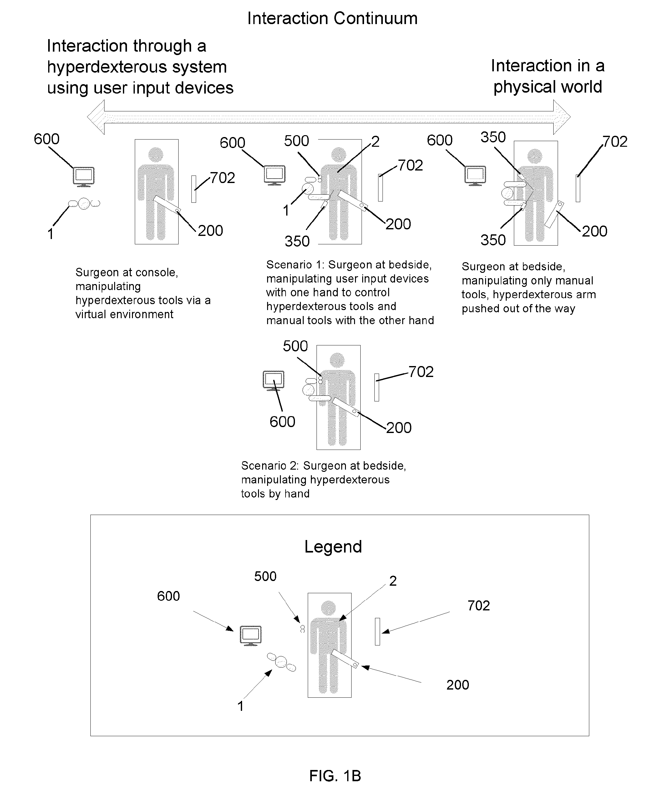
Additionally, from this remote location (at the console), the surgeon cannot simultaneously use manual tools while controlling the robot arm.
Some tasks such as executing large scale motion of the robotic tools from one surgical site to another surgical site in a patient's body become more difficult due to the interference of components of the robotic arms.
Some tasks easily performed with manual tools are more complex or impossible to perform with robotic tools.
For example, in some cases, the robot simply does not have an end effector capable of accomplishing the task.
Some tasks requiring tactile feedback, such as palpation, cannot be done by the surgeon operating the robotic arm.
The cables which articulate the end effector twist during rotation, thus causing friction and binding of the cables.
This twisting also causes a limitation on the range of rotation, typically limited to approximately + / −270° of rotation.
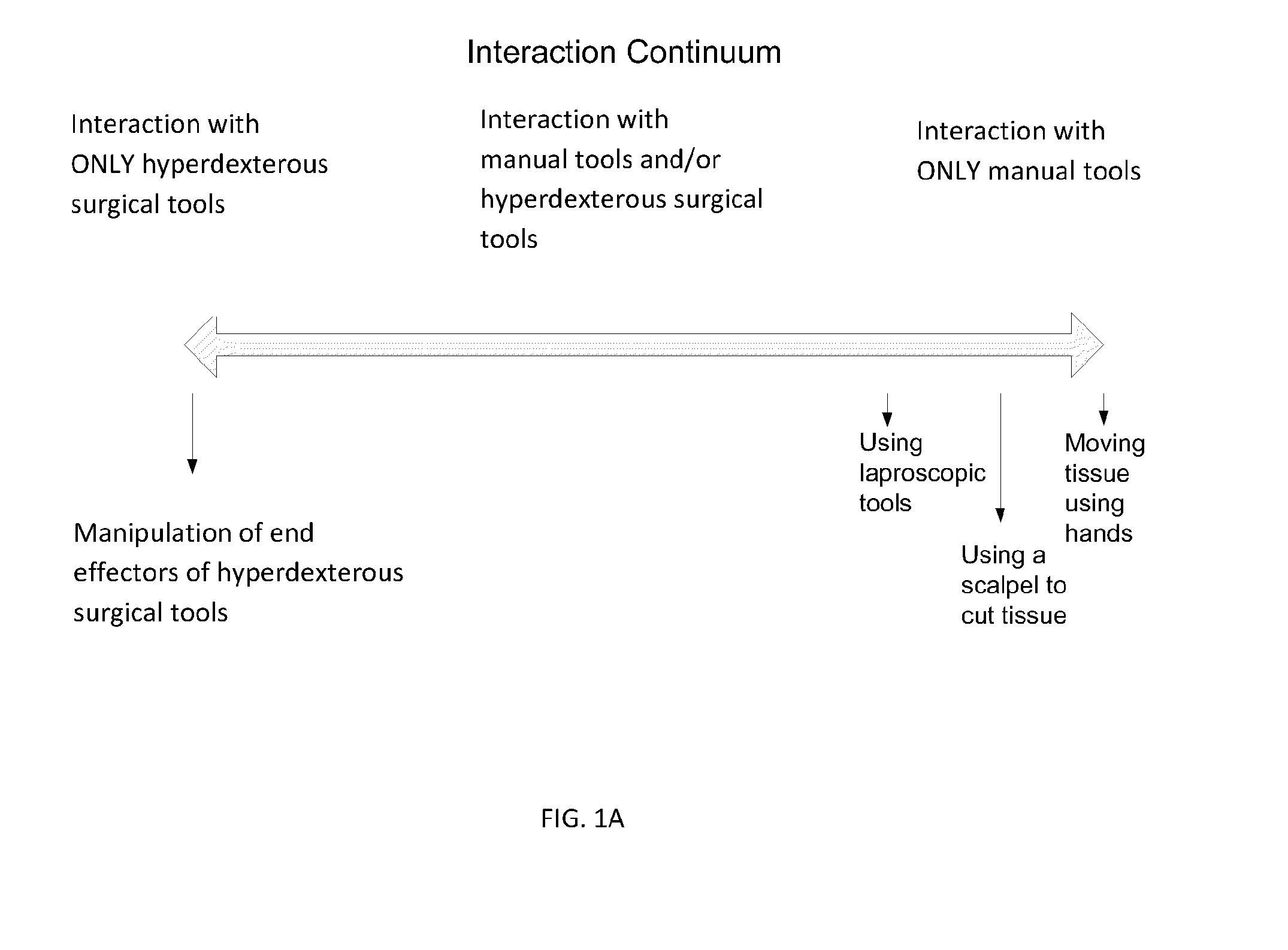
One drawback of the current modes of minimally invasive surgery discussed above is that they are discrete.
In order for the surgeon to use manual tools at the operating table, he or she cannot be controlling the robotic arm at a remote console.
The surgeon cannot simultaneously control both robotic tools and manual tools.
Another drawback of the current modes of minimally invasive surgery is that they provide limited information to the surgeon.
Typically this information is limited to the view of a robotic camera.
Another drawback with on-market robotic surgical systems is that they do not allow the surgeon the ability to reposition him or herself during surgery.
Another drawback of on-market robotic surgical systems is that they are typically anchored to the ground and do not follow the orientation of the patient during the course of surgery.
Another drawback with on-market robotic arms is that accessing the workspace may require the robotic arms to move through a very large range of motion.
The movement may be limited when multiple robotic arms are used for a single surgery.
The chances of collision between the robotic arms or components of a single robotic arm increases.
The challenge is to maximize the work space inside the body while maximizing the free space outside of the patient, while also keeping the robotic system small and compact.

Method used


Image

  • Hyperdexterous surgical system
  • Hyperdexterous surgical system
  • Hyperdexterous surgical system

Examples


an embodiment

of a Surgical Method

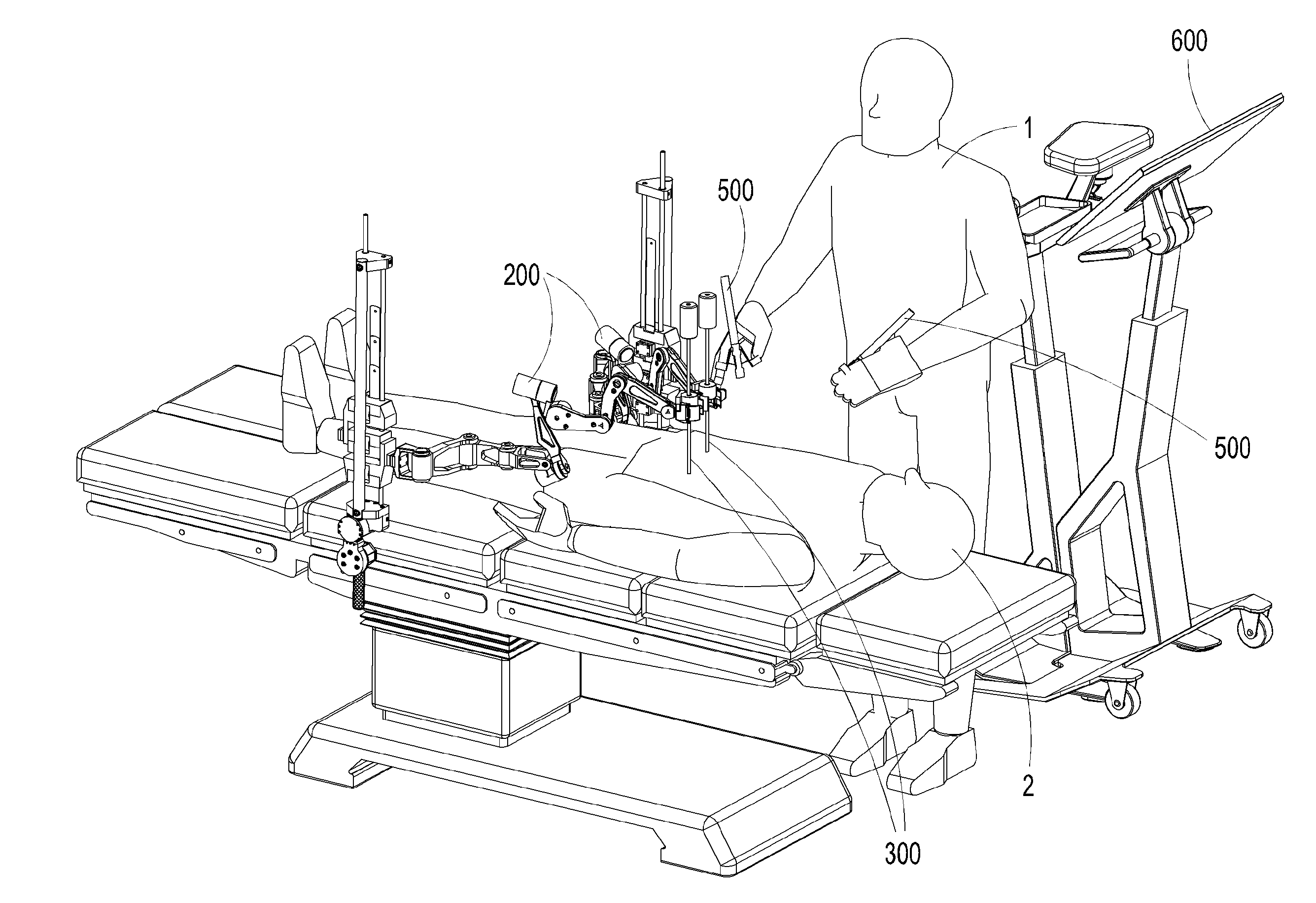
[0343]In some embodiments, one or more manual tools 350 are used in conjunction with one or more hyperdexterous surgical tools 300 in the same work space. An example of a manual tool 350 is a stapler 354, see FIG. 39. The stapler 354 may be used in conjunction with the hyperdexterous surgical tool 300. The workflow when using both types of tools in a colon resection surgical procedure is shown in FIG. 39, which shows a method 5. FIG. 39 illustrates one method of using a hyperdexterous surgical tool 300 and a manual tool 350. The method relates to holding the colon in a particular position and placing a staple line across the colon. The system includes a first grasper 312, a second grasper 314, a camera 304, and a stapler 354. The system includes two input devices 500, a first controller 516 and a second controller 518.

[0344]In step 10, the operator 1 may position the camera 304 by using any of the input devices 500. In some embodiments, the operator 1 connects an...


PUM


Abstract

A hyperdexterous surgical system is provided. The system can include one or more surgical arms coupleable to a fixture and configured to support one or more surgical tools. The system can include an electronic control system configured to communicate electronically with the one or more robotic surgical tools. The control system can electronically control the operation of the one or more surgical tools. The system can include one or more portable handheld controllers actuatable by a surgeon to communicate one or more control signals to the one or more surgical tools via the electronic control system to operate the one or more surgical tools. The one or more portable handheld controllers can provide said one or more control signals from a plurality of locations of an operating arena, allowing a surgeon to be mobile during a surgical procedure and to remotely operate the one or more surgical tools from different locations of the operating arena.

Description

INCORPORATION BY REFERENCE TO ANY PRIORITY APPLICATIONS[0001]This application is a continuation application of U.S. Ser. No. 14 / 388,180 filed Sep. 25, 2014, which is a US National Phase of International Application No. PCT / US2014 / 026115 filed Mar. 13, 2014 designating the US and published in English on Sep. 25, 2014 as WO 2014 / 151621, which claims the priority benefit under 35 U.S.C. §119(e) of U.S. Provisional Application No. 61 / 791,248 filed Mar. 15, 2013, U.S. Provisional Application No. 61 / 906,802 filed Nov. 20, 2013, U.S. Provisional Application No. 61 / 908,888 filed Nov. 26, 2013, U.S. Provisional Application No. 61 / 915,403 filed Dec. 12, 2013, and U.S. Provisional Application No. 61 / 935,966 filed Feb. 5, 2014, all of which are hereby incorporated by reference in their entirety and should be considered a part of this specification.BACKGROUND[0002]1. Field[0003]Surgical robots allow surgeons to operate on patients in a minimally invasive manner. The present application relates t...

Claims


Application Information

Patent Timeline
Patent Type & Authority Applications(United States)
IPC IPC(8): A61B19/00
CPCA61B2019/2223A61B19/2203A61B19/20A61B19/201A61B19/26A61B19/5212A61B19/5225A61B19/56A61B2017/00207A61B2017/00221A61B2019/2238A61B2019/2269A61B2019/268A61B2019/5227A61B90/361A61B34/30A61B90/11A61B2090/571A61B34/37A61B2034/306A61B34/74A61B90/60A61B90/37A61B2090/371A61B17/32A61B34/71A61B90/50G05B2219/39135A61B90/10A61B34/25
Inventor KILROY, PABLO EDUARDO GARCIAEGAN, THOMAS D.KOENIG, KAREN SHAKESPEAR
Owner SRI INTERNATIONAL
Learn More