Work vehicle boom assembly providing improved visability

a technology for working vehicles and booms, which is applied in the direction of mechanical machines/dredgers, soil-shifting machines/dredgers, transportation and packaging, etc. it can solve the problems of poor operator visibility to the area being worked, the boom interferes with, if not almost completely blocks, and the sightline between the vehicle cabin and the implement is another obstacle, so as to achieve the effect of better sight lin

Inactive Publication Date: 2015-01-22
DEERE & CO
View PDF10 Cites 39 Cited by
  • Summary
  • Abstract
  • Description
  • Claims
  • Application Information

AI Technical Summary

Benefits of technology

[0008]An improved boom construction, and work vehicle having an improved boom, is disclosed that affords the vehicle operator a better line of sight to the work tool implement and the area being worked. The boom mounts the implement at one end and has a split end in which two branches angle outwardly away from each other leaving an open space between the branches. The boom is mounted such that the pivotal connection is located at the branches of the boom and the opening extends beyond the pivot axis of the boom. This arrangement creates a window for a sightline between the vehicle and the implement such that the vehicle operator can view the implement and work area behind the vehicle.

Problems solved by technology

Yet even then, in conventional fixed boom assemblies the boom interferes with, if not almost entirely blocks, the operator's line of sight to the implement.
The mounting position and height of the boom and the large, heavy-duty construction required for the boom and boom support components further exacerbate the problem of poor operator visibility to the area being worked.
Furthermore, the additional elevated pivot connection often found in dual function booms creates another obstacle in the sightline between the vehicle cabin and the implement.

Method used


Image

  • Work vehicle boom assembly providing improved visability
  • Work vehicle boom assembly providing improved visability
  • Work vehicle boom assembly providing improved visability

Examples


Embodiment Construction

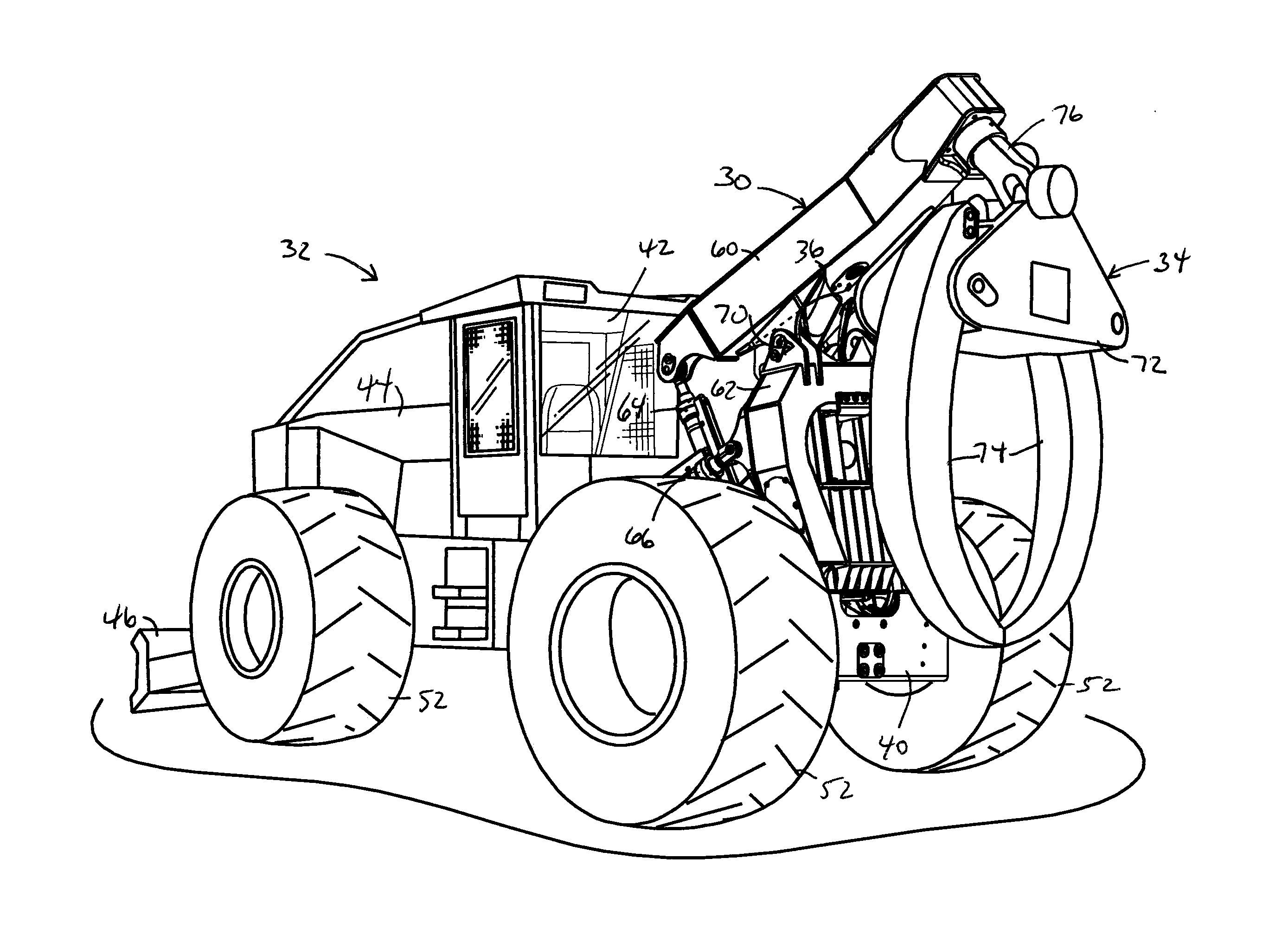
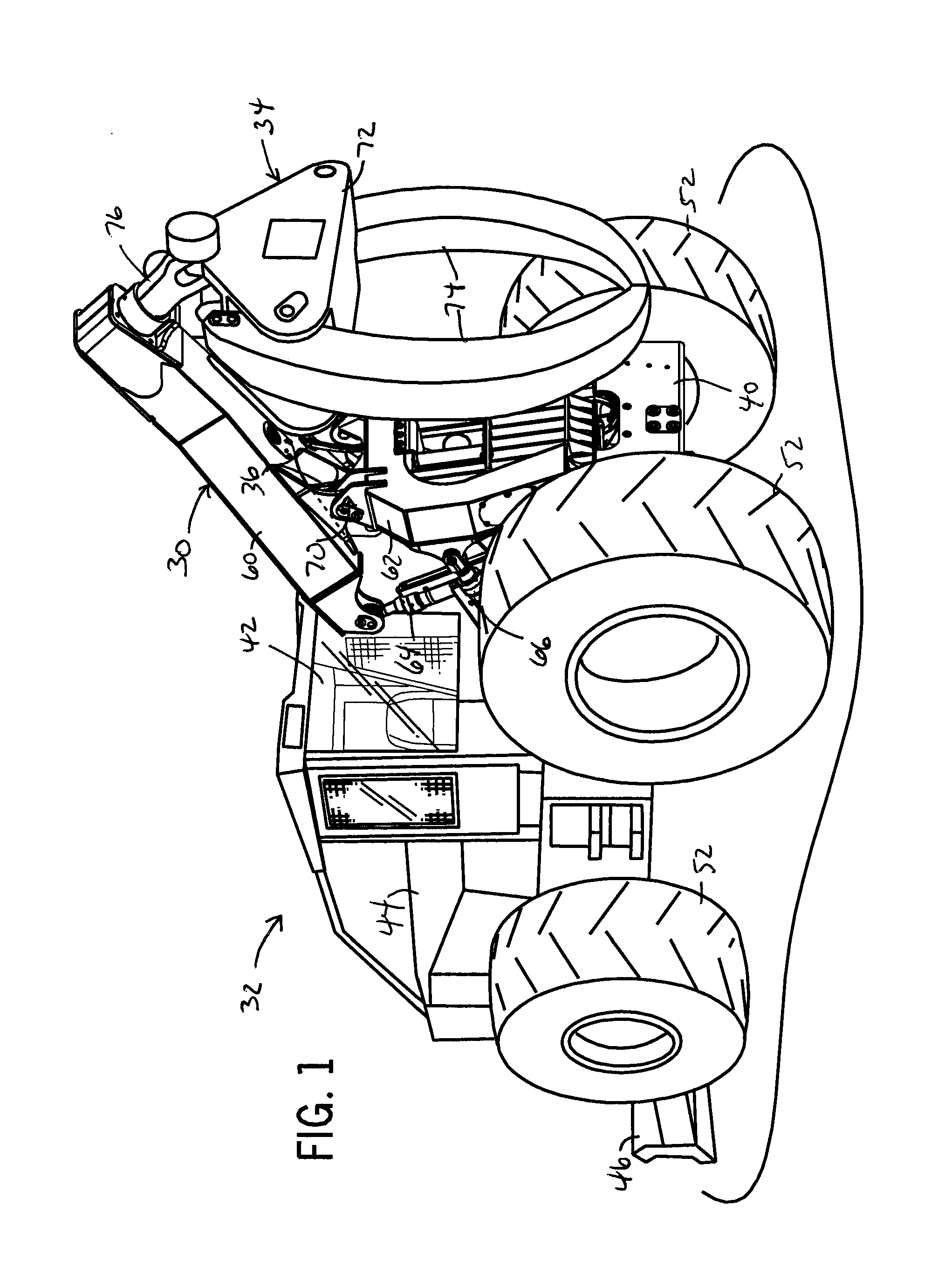
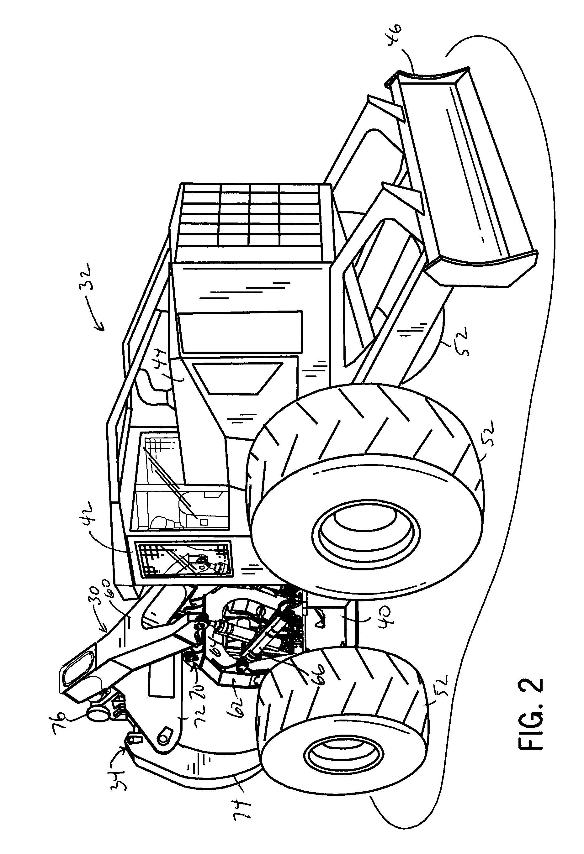
[0027]The following describes one or more example constructions of a boom assembly 30 and work vehicle 32, as shown in the accompanying figures of the drawings described briefly above. Various modifications to the example construction(s) may be contemplated by one of skill in the art.

[0028]FIGS. 11-14 show an example application of the boom assembly 30 incorporated into the work vehicle 32 which powers and controls an implement attachment 34 through a bundle of electric and hydraulic working lines 36. In the example shown in FIGS. 1-5 and described herein, the work vehicle 32 is a skidder and the implement attachment 34 is a grapple. For simplicity a single machine and attachment are described herein as an example application. However, the boom assembly 30 can be utilized with various work vehicles and implements, including with tractors and other agricultural, forestry or construction vehicles with any applicable implement attachment. As such, the terms “work vehicle” and “implemen...


PUM


Abstract

A work vehicle has a boom assembly for a work implement that provides an improved sightline between the cabin and work implement. The boom assembly can be a dual function boom having a wishbone configuration with an elongated body supporting the work implement and at the other end having branch sections extending outwardly at acute angles with open space therebetween. A boom support arch can provide an elevated boom mount on which the boom can pivot about a boom pivot axis at pivots located on the branches of the boom. The boom support arch can have its own pivotal mounting connection to the work vehicle. Actuators, such as hydraulic cylinders, can be coupled to the boom and support arch to independently pivot the boom and the support arch with respect to each other and the work vehicle.

Description

CROSS-REFERENCE TO RELATED APPLICATION(S)[0001]Not applicable.STATEMENT OF FEDERALLY SPONSORED RESEARCH OR DEVELOPMENT[0002]Not applicable.FIELD OF THE DISCLOSURE[0003]This disclosure relates to work vehicles and booms for work vehicles that support and position implements attached thereto.BACKGROUND OF THE DISCLOSURE[0004]Work vehicles known as skidders are heavy-duty vehicles used in the forestry industry to gather and clear logs. Cable skidders use a winch line to wrap around and winch the logs together so that the skidder can drag them to the landing area. Grapple skidders have a grapple mounted on a boom at the rear of the vehicle that the vehicle operator controls, using onboard controls and actuation systems, to raise, lower, and rotate the grapple as well as open and close the grapple tongs as needed to clamp around the logs that are to be dragged away by the skidder.[0005]Grapple skidders generally come in one of three types based on the type of boom employed. The booms of ...

Claims


Application Information

Patent Timeline
Patent Type & Authority Applications(United States)
IPC IPC(8): E02F3/38
CPCE02F3/38A01G23/003A01G23/006E02F3/301B66C1/68E02F3/42B66C1/585
Inventor CARR, ROBERT T.JEREW, TIMOTHY L.FICHTINGER, GARY R.BIHL, DANIEL F.
Owner DEERE & CO
Why Eureka
Try Eureka