
Smart Webcam Device in Distributed Circuit Casings and Cable-Encapsulating Neck Structure

a distributed circuit and webcam technology, applied in the field of portable electronic devices, can solve the problems of not including webcams in many larger computer display models, still not featuring windshield-facing video recording equipment as standard features, and cannot be adjusted to a stable position

Inactive Publication Date: 2015-01-15
HUANG JEFFREY
View PDF5 Cites 6 Cited by
  • Summary
  • Abstract
  • Description
  • Claims
  • Application Information

AI Technical Summary

Benefits of technology

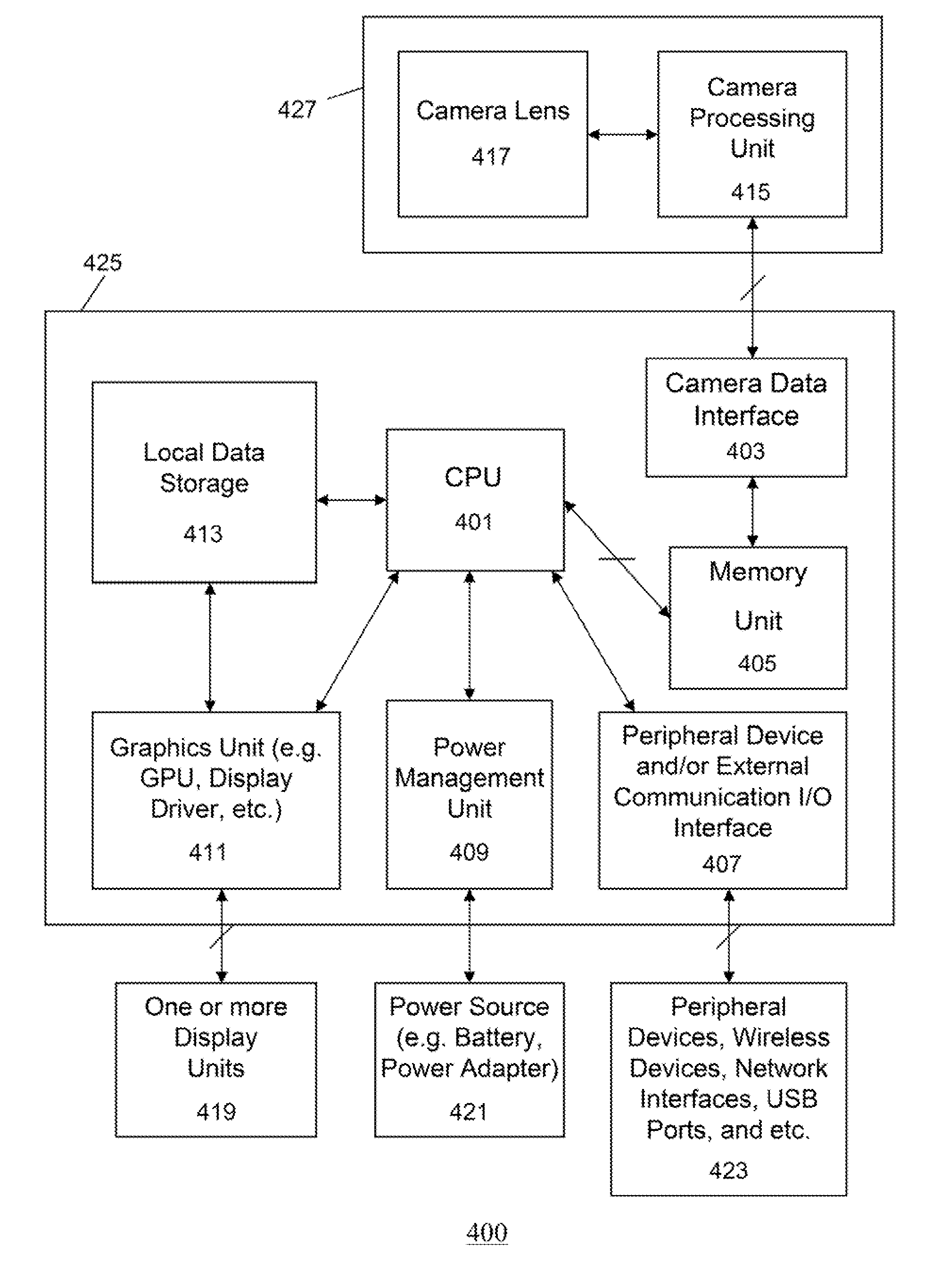
The present invention is about a smart webcam device that is made of two parts, namely a bottom housing and a top housing, which are connected by a cable-encapsulating neck structure. The bottom housing has network communication-capable computing circuitry and a camera data interface, while the top housing has a webcam-specific circuitry that includes a camera lens, a camera processing unit, and a webcam unit interface. The neck structure encapsulates a data communication and power cable that connects the two parts, and also includes a webcam hanger that protrudes from the edge of the neck structure. The innovation of this design is that it allows for swivel-capable rotation of the webcam device, making it more versatile and easier to use.

Problems solved by technology

However, there are numerous electronic devices that still do not embed webcams despite the convenience of integrating them.
Likewise, many larger computer display models still do not incorporate webcams.
Furthermore, vehicles that can benefit from incorporation of webcams for evidence-gathering purposes (i.e. in case of accidents or illegal activities) still do not feature windshield-facing video-recording equipment as standard features.
Equally important, a conventional “slab” casing webcam equipment does not stand on its own on a flat ground, and cannot be adjusted to a stable position, unless a dedicated mounting unit is utilized.

Method used


Image

  • Smart Webcam Device in Distributed Circuit Casings and Cable-Encapsulating Neck Structure
  • Smart Webcam Device in Distributed Circuit Casings and Cable-Encapsulating Neck Structure
  • Smart Webcam Device in Distributed Circuit Casings and Cable-Encapsulating Neck Structure

Examples


Embodiment Construction

[0014]Specific embodiments of the invention will now be described in detail with reference to the accompanying figures. Like elements in the various figures are denoted by like reference numerals for consistency.

[0015]In the following detailed description of embodiments of the invention, numerous specific details are set forth in order to provide a more thorough understanding of the invention. However, it will be apparent to one of ordinary skill in the art that the invention may be practiced without these specific details. In other instances, well-known features have not been described in detail to avoid unnecessarily complicating the description.

[0016]The detailed description is presented largely in terms of procedures, logic blocks, processing, and / or other symbolic representations that directly or indirectly resemble one or more smart webcam devices in distributed circuit casings and cable-encapsulating neck structures. These process descriptions and representations are the mean...


PUM


Abstract

Various embodiments of a novel smart webcam device in distributed circuit casings and cable-encapsulating neck structure are disclosed. In one embodiment, the novel smart webcam device has a bottom housing that contains a network communication-capable computing circuitry, a top housing that contains a webcam-specific circuitry (e.g. a camera lens and a camera processing unit), and a cable-encapsulating neck structure interposed between the bottom housing and the top housing that uniquely encapsulates a data communication and power cable, which connects a camera data interface in the bottom housing and a webcam unit interface in the top housing. Preferably, the top housing and the bottom housing are swivel-capable around the cable-encapsulating neck structure. The novel smart webcam device is internally capable of transforming raw multimedia data captured from the webcam-specific circuitry into processed multimedia data in standardized formats, and can also transmit the processed multimedia data over a data network.

Description

BACKGROUND OF THE INVENTION[0001]The present invention generally relates to portable electronic devices. More specifically, the invention relates to one or more smart webcam devices in distributed circuit casings and cable-encapsulating neck structures. Furthermore, the invention also relates to a novel casing structure suitable for a multi-purpose usage of a smart webcam device. In addition, the invention also relates to a multi-segment casing structure that is appropriately weight-balanced for multi-purpose usage and operational durability.[0002]Conventional “webcam” devices are typically computer-mounted or display-mounted electronic devices, each with a camera lens to capture one or more images, videos, and / or other multimedia content visible and recordable through the camera lens. With various video capturing and multimedia applications becoming ubiquitous and popular, many personal computers (PC's), portable electronic devices, and building structures, and vehicles are being m...

Claims


Application Information

Patent Timeline
IPC IPC(8): H04N5/232H04N5/225
CPCH04N5/23222H04N5/2252H04N23/661H04N23/50H04N23/64H04N23/51
Inventor HUANG, JEFFREY
Owner HUANG JEFFREY
Learn More