
Index scan device and index scan method

a technology of index scan and index scan, applied in the field of index scan technique, can solve the problems of inefficiency of index scan and long time period, and achieve the effect of increasing the speed of index scan

Active Publication Date: 2015-01-08
NEC CORP
View PDF10 Cites 17 Cited by
  • Summary
  • Abstract
  • Description
  • Claims
  • Application Information

AI Technical Summary

Benefits of technology

The invention aims to solve the problem of slow index scan speeds in multi-dimensional range searches. It provides a technique to increase the speed of these searches by optimizing the indexing process.

Problems solved by technology

However, with the method described above, there is a possibility that the index scan becomes inefficient.
In such a case, all the partial spaces are required to be checked to see if these partial spaces overlap with the search space, and hence, a long period of time is required to extract partial spaces that overlap with the search space in the index scan.
This kind of problem arises from distortion occurring when the multi-dimensional space is changed to be one-dimensional.
This type of problem becomes prominent, for example, in the case where the number of dimensions that a target to be searched has is large or in the case where there is a difference between the widths of the dimension ranges each set for searching.

Method used


Image

  • Index scan device and index scan method
  • Index scan device and index scan method
  • Index scan device and index scan method

Examples


first exemplary embodiment

[Operation and Effect of First Exemplary Embodiment]

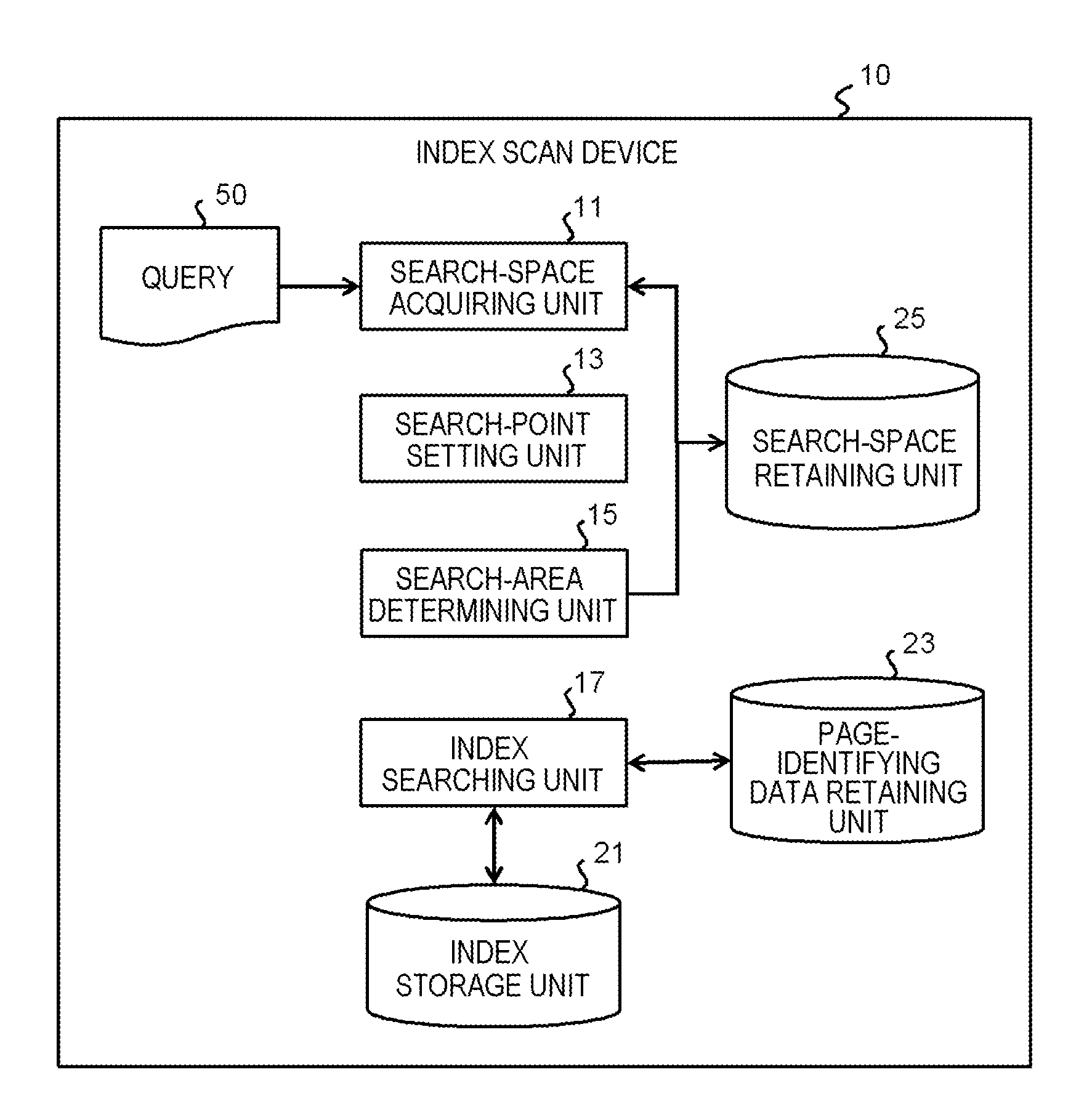
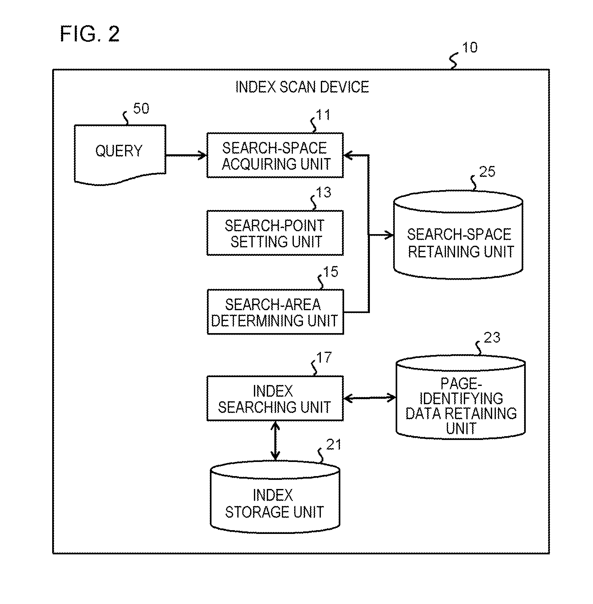
[0052]As described above, in the first exemplary embodiment, in the index storage unit 21, when the index data corresponding to the partial space overlapping with the search space are searched for, index data corresponding to the partial space containing the data point corresponding to at least one of the minimum and the maximum of binary numbers obtained by converting each of the data points in the multi-dimensional space into one dimension are identified. Then, on the basis of identification information (position and range) on the corresponding partial space obtained from the identified index data, how the entire multi-dimensional space is spatially divided is estimated. With this estimation, information on the boundary line passing through the search space is acquired, and information on the partial search space obtained by dividing, by the boundary line, the remaining space (untracked search space) excluding the identified part...

example

[0054]Below, an example of the exemplary embodiment will be described more specifically. In the following Example, an example is given in which the search target space having the database mapped thereinto is two-dimensional; this two-dimensional space is converted into one-dimension through the Z-order curve (space-filling curve); each of the data points is expressed in binary form; and this two-dimensional space is spatially divided through KD-Tree.

[0055]FIG. 4 is a diagram schematically illustrating a two-dimensional space and a two-dimensional search range mapped in a database in Example. Note that, hereinbelow, the horizontal axis in FIG. 4 is referred to as X axis and the vertical axis is referred to as Y axis. The thick line in FIG. 4 indicates the boundary line of the spatial division, and the thick dotted line in FIG. 4 indicates the search space. Each of the data points in the two-dimensional space is identified with binary numbers illustrated in FIG. 4 (the upper line show...


PUM


Abstract

The index scan device acquires information on a search space in a multi-dimensional space corresponding to a search range of a query, or information on a partial search space in this search space; sets, as a search point, a data point corresponding to at least one of a minimum and a maximum of values obtained by changing each data point in the multi-dimensional space to be one-dimensional, from among data points contained in the search space or the partial search space; identifies, in the index storage unit, index data associated with a partial space containing the search point; estimates a boundary line passing through the search space or the partial search space on the basis of identification information on the partial space obtained from the identified index data; and determines, from among divided search spaces obtained by dividing the search space or the partial search space by the estimated boundary line, a divided search space excluding the partial space containing the search point as the partial search space.

Description

TECHNICAL FIELD[0001]The present invention relates to an index scan technique used in multi-dimensional range search applied to a database mapped in a multi-dimensional space divided into plural partial spaces.BACKGROUND ART[0002]As the number of data increases, scalable distributed databases have been proposed. Most of these distributed databases realize the scalability by supporting only simple query processes such as range search only in one dimension. Further, a distributed database is proposed in which range search in plural dimensions is made possible by mapping multi-dimensional values into one-dimensional values (Non-Patent Document 1 described below).[0003]The method of the multi-dimensional range search, proposed in Non-Patent Document 1 described below, first acquires a data point indicating the maximum value (hereinafter, referred to as a maximum data point) and a data point indicating the minimum value (hereinafter, referred to as a minimum data point) from among data p...

Claims


Application Information

Patent Timeline
IPC IPC(8): G06F17/30
CPCG06F17/3087G06F17/30333G06F16/2264G06F16/2246G06F16/9537
Inventor NISHIMURA, SHOJI
Owner NEC CORP
Learn More