
Antenna tilt optimization in a wireless communications network

a wireless communication network and antenna tilt technology, applied in the direction of network planning, electrical equipment, wireless communication, etc., can solve the problems of affecting cellular service and redirecting calls

Active Publication Date: 2015-01-08
NOKIA SOLUTIONS & NETWORKS OY
View PDF12 Cites 9 Cited by
  • Summary
  • Abstract
  • Description
  • Claims
  • Application Information

AI Technical Summary

Benefits of technology

This patent is about a system, device, and method for optimizing the tilt of a cellular base station antenna. The system collects information about neighboring cells and analyzes this information to suggest or implement changes to the antenna tilt. This approach helps to find sub-optimal antenna tilt configurations and improve network performance. The collected information includes information about the cells' activity, signal strength, and distance to the source cell. Adjusting the antenna can include changing the tilt angle or transmit power. Overall, this patent provides a technical solution for improving the performance and efficiency of cellular networks.

Problems solved by technology

All of these changes to environmental conditions can affect cellular service over time.
In some cases, calls will be redirected to an alternate Radio Access Technology (RAT) due to lack of coverage optimization.
For example, calls may be directed to 2G because of inadequate 3G coverage due to excessive downtilt of antennas carrying 3G signals.

Method used


Image

  • Antenna tilt optimization in a wireless communications network
  • Antenna tilt optimization in a wireless communications network
  • Antenna tilt optimization in a wireless communications network

Examples


Embodiment Construction

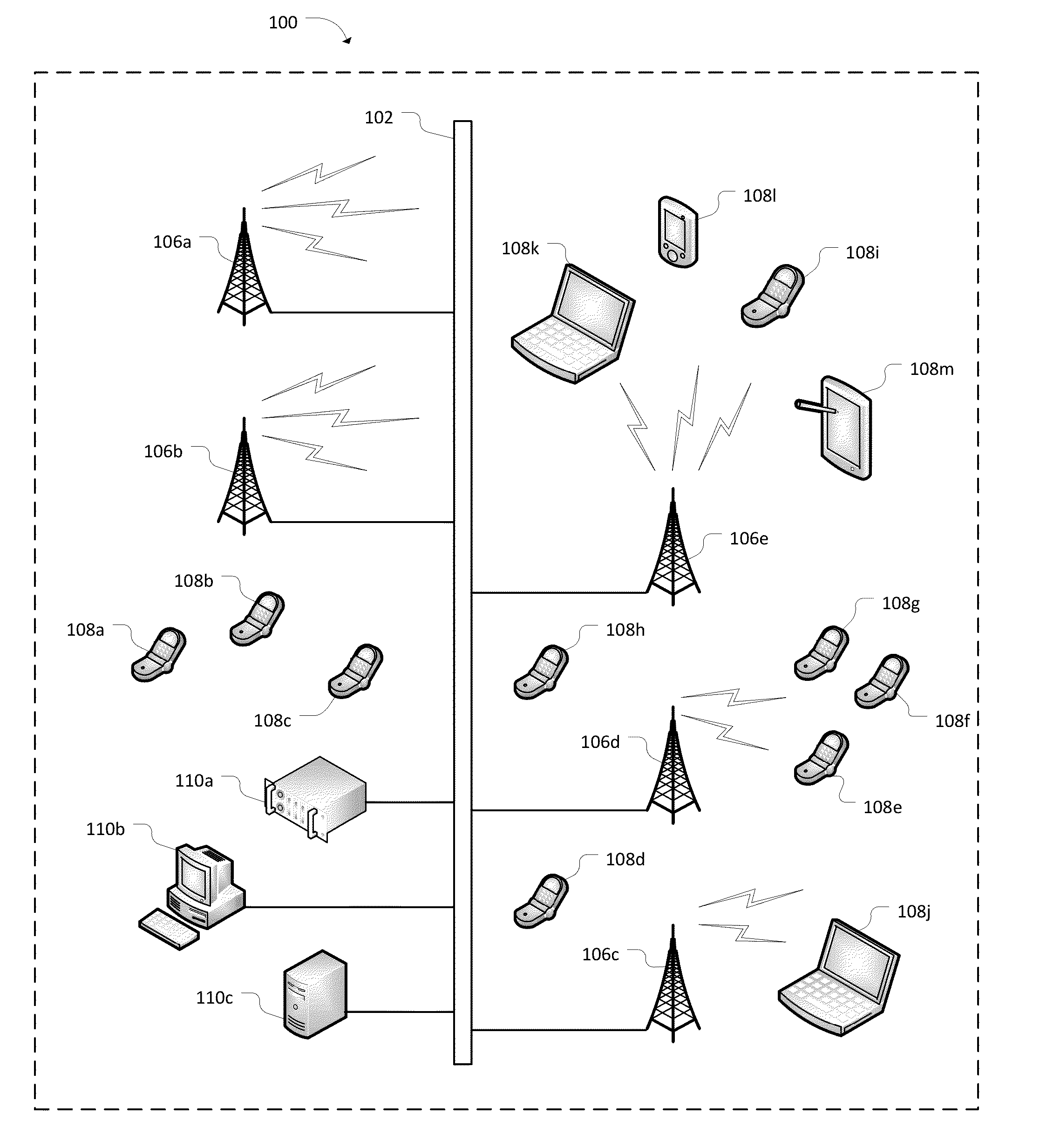
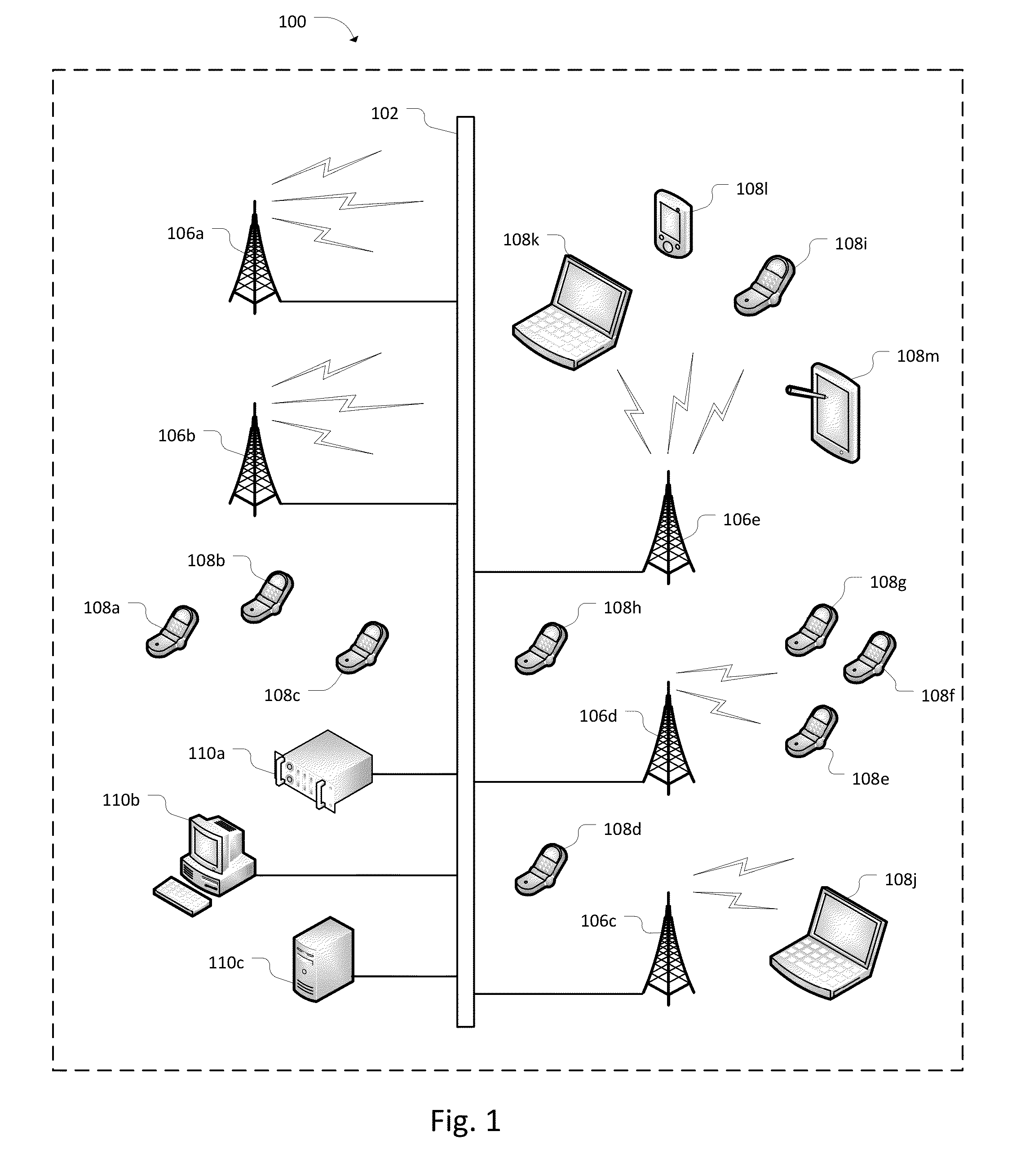
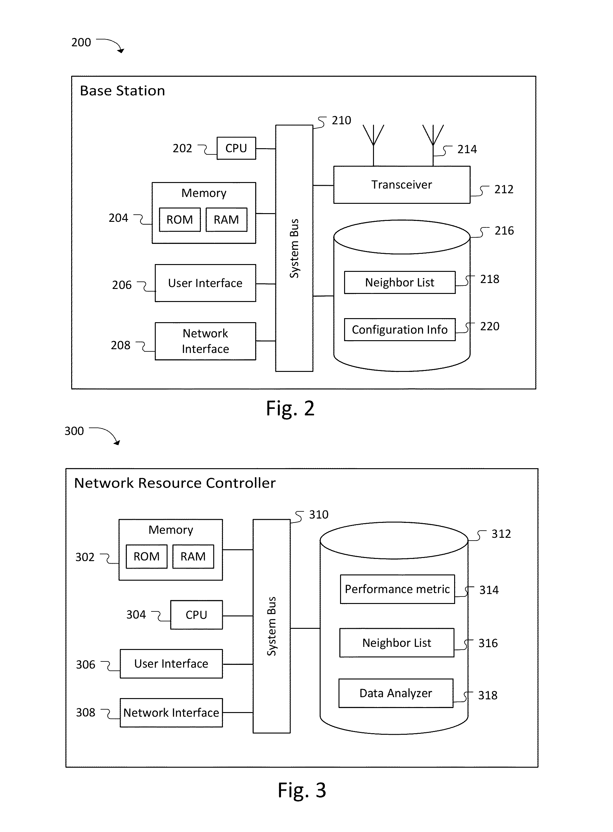
[0029]In the following detailed description, reference is made to the accompanying drawings, which form a part of the description. The example embodiments described in the detailed description, drawings, and claims are not meant to be limiting. Other embodiments may be utilized, and other changes may be made, without departing from the spirit or scope of the subject matter presented herein. It will be understood that the aspects of the present disclosure, as generally described herein and illustrated in the drawings, may be arranged, substituted, combined, separated, and designed in a wide variety of different configurations.

[0030]The invention can be implemented in numerous ways, including as a process; an apparatus; a system; a composition of matter; a computer program product embodied on a computer readable storage medium; and / or a processor, such as a processor configured to execute instructions stored on and / or provided by a memory coupled to the processor. In general, the orde...


PUM


Abstract

Optimization of a wireless communications network may be accomplished by collecting information for a plurality of target cells neighboring a source cell, calculating a tilt score based on the collected information, and adjusting an antenna of the source cell based on the tilt score.

Description

CROSS-REFERENCES TO RELATED APPLICATIONS[0001]This disclosure claims priority to U.S. Provisional Application No. 61 / 842,335, filed Jul. 2, 2013, which is incorporated by reference herein.BACKGROUND OF THE INVENTION[0002]As technology advances, more and more data is transferred over cellular telecommunications networks. The number of subscribers continues to grow, as does the number user equipment (UE) utilizing wireless communication channels. In addition, as streaming services become more sophisticated and popular, the amount of data communicated between UE and base stations of a cellular network continues to grow. Cellular providers are regularly adding new equipment and optimizing existing equipment in order to keep pace with the increasing demands.[0003]Cellular communications are affected by a variety of environmental conditions. Foliage develops during spring and recedes in the fall. Man-made structures are built and destroyed. Geographic features are altered by human and nat...

Claims


Application Information

Patent Timeline
IPC IPC(8): H04W16/28
CPCH04W16/28H04W24/02H04W16/02H04W16/24
Inventor WELLINGTON, DANIEL
Owner NOKIA SOLUTIONS & NETWORKS OY
Learn More