Highly efficient power supply unit and method for supplying power using same

Active Publication Date: 2015-01-08
NAVER CLOUD CORP
View PDF4 Cites 11 Cited by
  • Summary
  • Abstract
  • Description
  • Claims
  • Application Information

AI Technical Summary

Benefits of technology

Example embodiments provide a power supply device and method that can reduce or prevent data loss caused by power supply unit failure, blackouts, and overload. Additionally, it can efficiently supply power by minimizing power usage and prevent voltage drop during switching input voltage.

Problems solved by technology

Accordingly, when an error occurs in supplying power due to, for example, an overload, a blackout, the fault of a PSU, it may critically affect a server operation.
Also, the power efficiency may vary based on a state of a PSU individually used for each server and thus, it may be difficult to achieve the maximum effect.

Method used


Image

  • Highly efficient power supply unit and method for supplying power using same
  • Highly efficient power supply unit and method for supplying power using same
  • Highly efficient power supply unit and method for supplying power using same

Examples


Embodiment Construction

[0043]Hereinafter, some example embodiments will be described in detail with reference to the accompanying drawings.

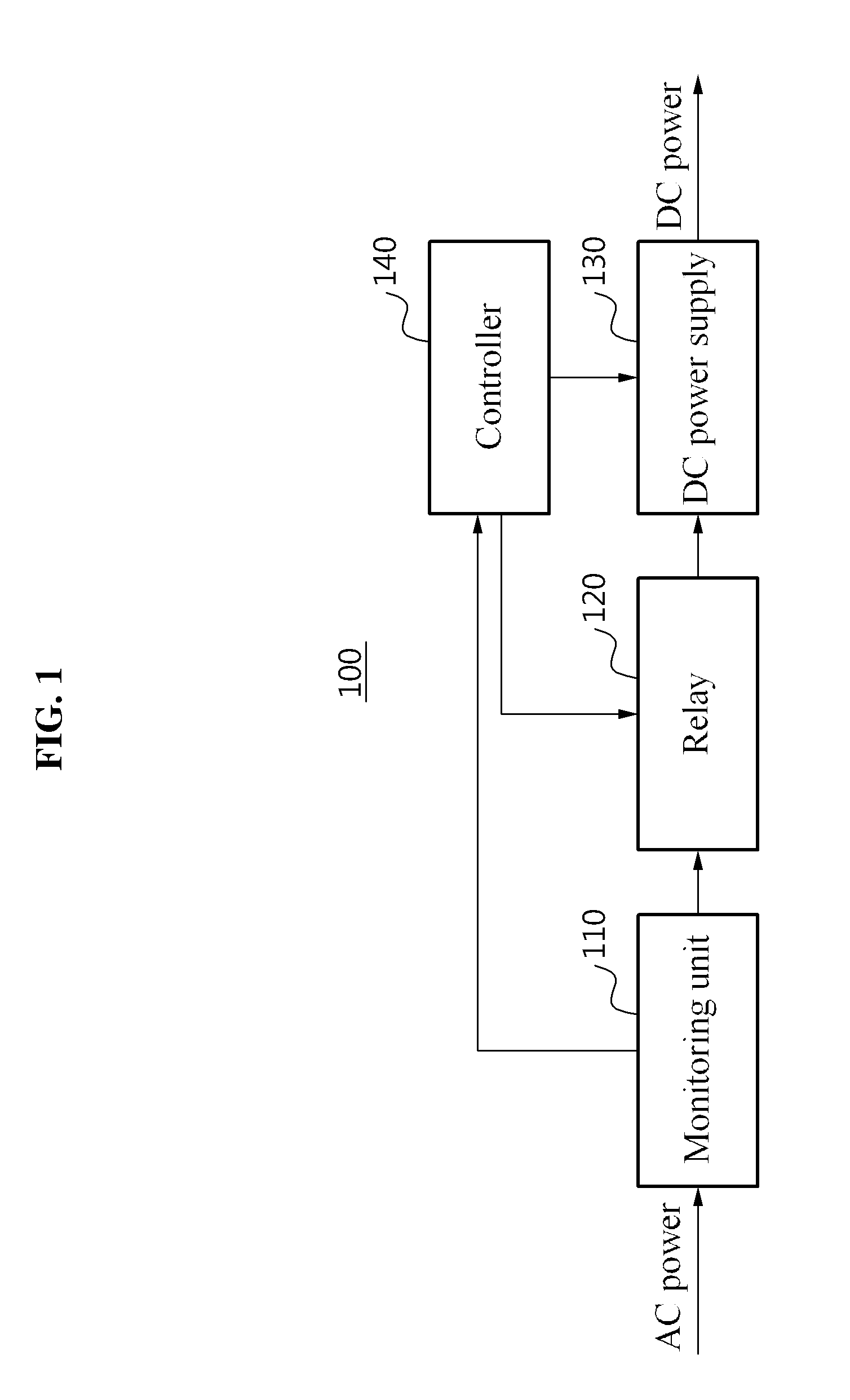
[0044]FIG. 1 is a block diagram illustrating a power supply device according to some example embodiments in more detail.

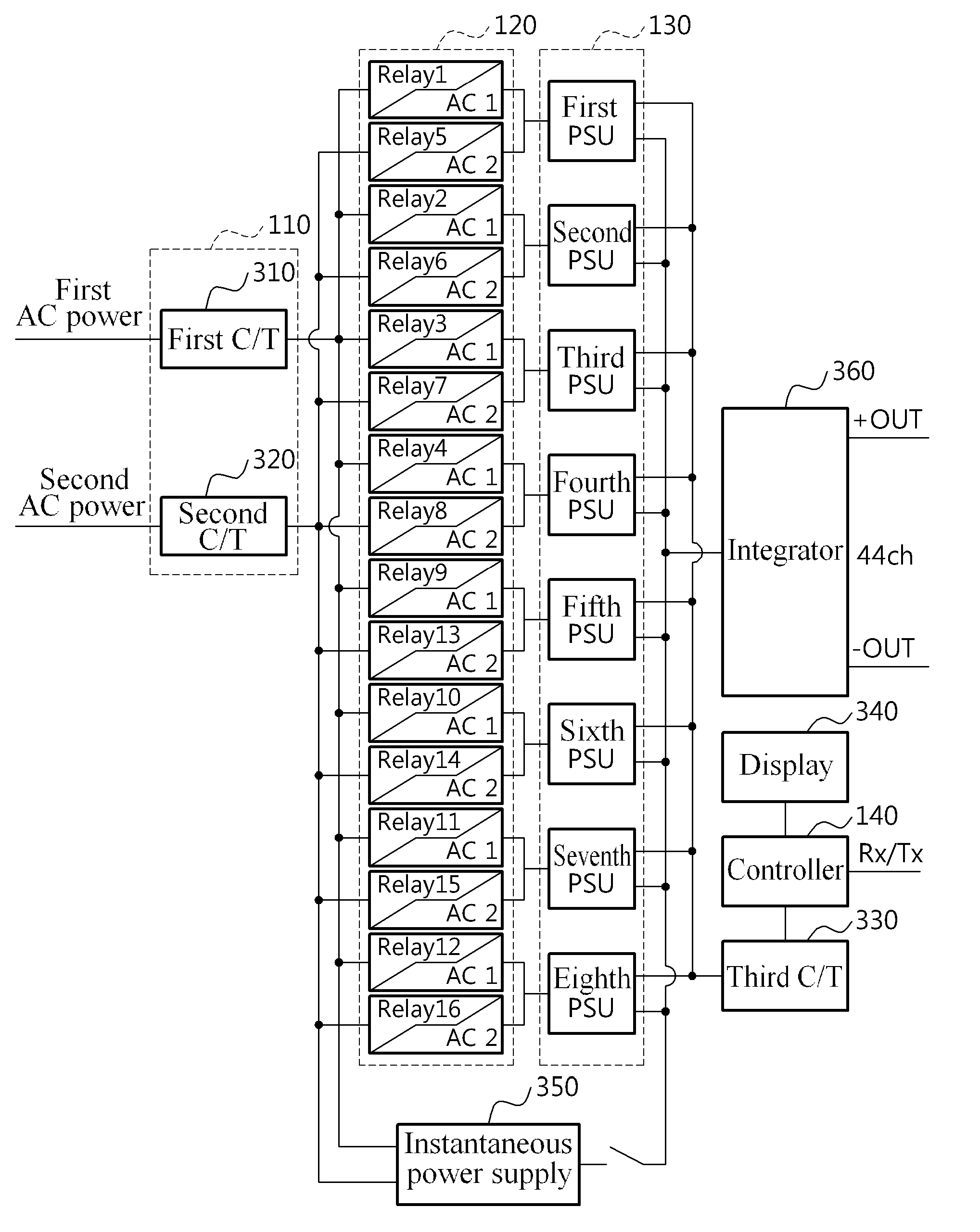
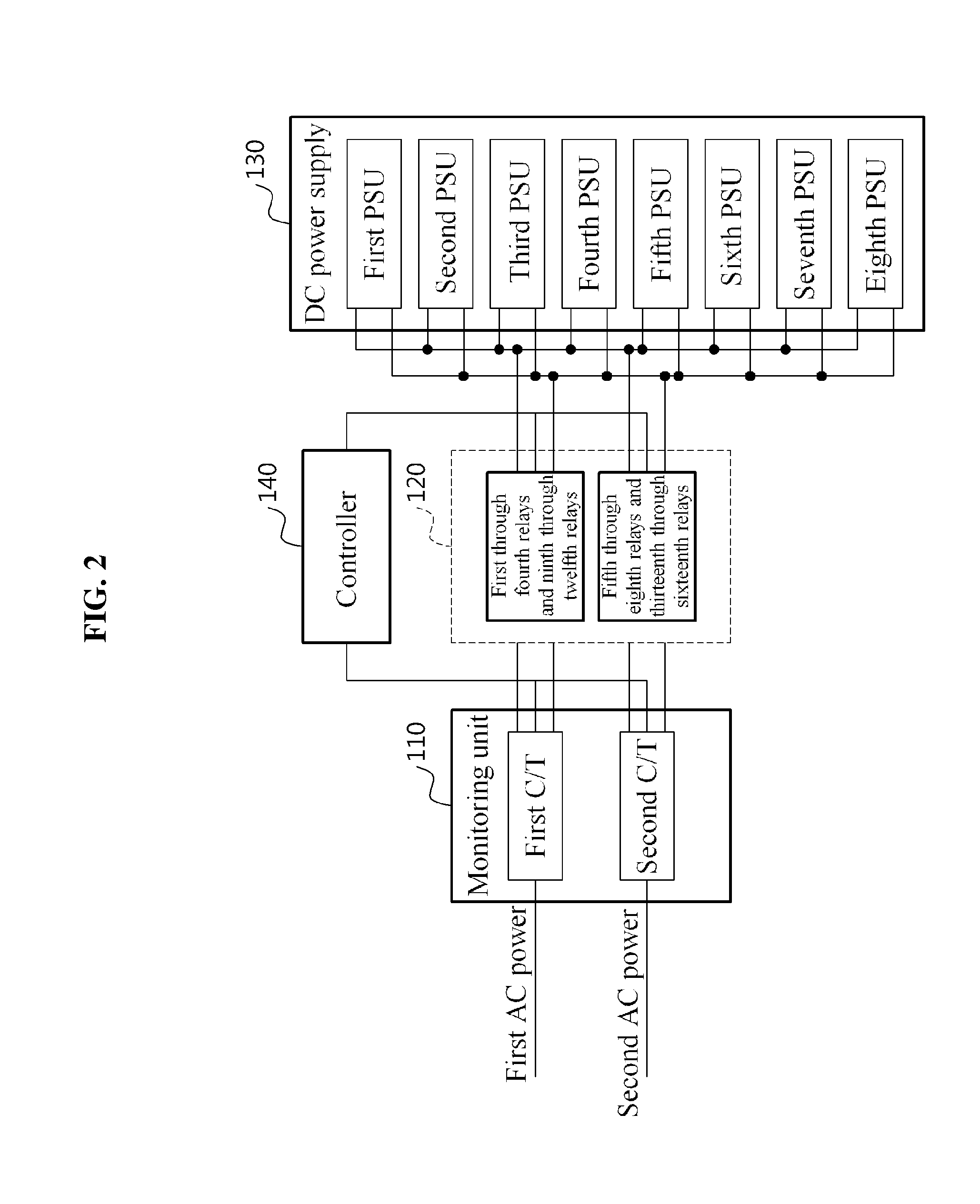
[0045]A power supply device 100 may supply stable direct current (DC) power based on a rack unit disposed in a data center, and may also maintain the power efficiency to be in an improved or optimal state. Referring to FIG. 1, the power supply device 100 may include a monitoring unit 110, a relay 120, a DC power supply 130, and / or a controller 140.

[0046]When unstable power is supplied to a rack due to, for example, an overload and a blackout, data recorded in a server may be lost. To prevent this, the power supply device 100 may receive alternating current (AC) power from a plurality of sources, may multiplex the received AC power, may convert the multiplexed AC power to DC power, and may supply the converted DC power to a plurality of racks.

[0047]As ...


PUM


Abstract

A more efficient power supply unit and a method for supplying power using same are disclosed. The power supply unit comprises a relay for switching alternating current power supplied from a plurality of sources; a direct current power supply for converting the switched current power to direct current power; and a controller for generating a switch signal to control the relay to switch the sources on the basis of the result for monitoring the alternating current power supplied from the sources.

Description

TECHNICAL FIELD[0001]Example embodiments relate to a highly efficient power supply device for supplying power to a rack and a power supply method using the same.BACKGROUND ART[0002]Recently, with the emergence of a large data center, research is ongoing to convert a data center based on an alternating current (AC) power transfer to a data center based on a more efficient direct current power transfer.[0003]In this regard, Korean Patent Laid-Open Publication No. 10-2011-003035, published on Jan. 11, 2011, titled “Direct current (DC) electric power supply system”, discloses technology in which a DC power supply system receives AC power and directly supplies, to a plurality of servers, DC power output from a rectifier configured to generate the DC power.[0004]However, the conventional power supply system uses an individual power supply unit (PSU) for each server. Accordingly, when an error occurs in supplying power due to, for example, an overload, a blackout, the fault of a PSU, it ma...

Claims


Application Information

Patent Timeline
IPC IPC(8): H02J3/00H02J7/00
CPCH02J7/0068H02J3/005G06F1/30H02J1/102H02J5/00H02J9/061H02J7/02H02J3/10
Inventor YOUN, YONG SOORYU, KEUN HO
Owner NAVER CLOUD CORP
Why Eureka
Try Eureka