
Structure of Tool Holding Sheath Cross Reference To Related Application

Inactive Publication Date: 2015-01-01
YUN CHAN IND
View PDF5 Cites 6 Cited by
  • Summary
  • Abstract
  • Description
  • Claims
  • Application Information

AI Technical Summary

Benefits of technology

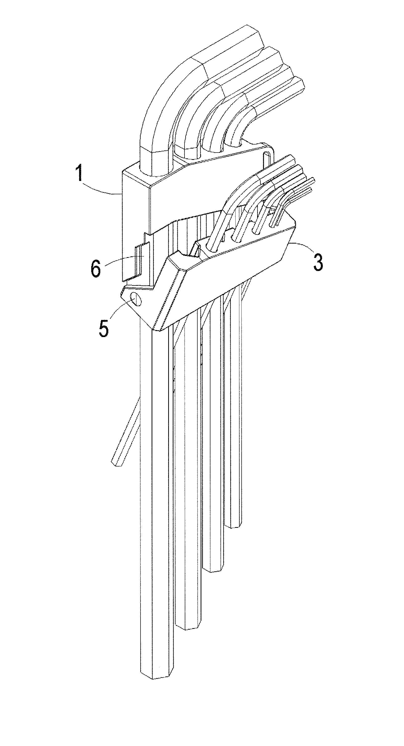
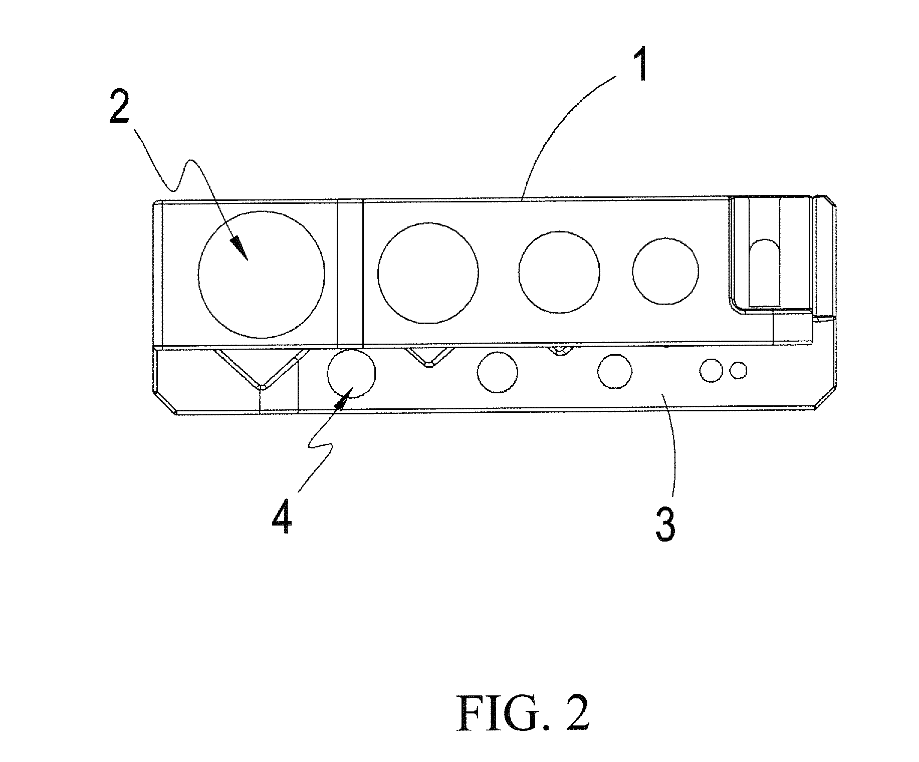
The present invention is a tool holding sheath that can accommodate wrench tools of different specifications and sizes. The structure of the sheath is designed to be simple, convenient, and low-cost. The sheath includes a first and second accommodation body that is pivoted together, with a pushing recess on one side and accommodation spaces on both bodies. The design also includes notches that allow for the partial volume of a wrench to be accommodated at a corresponding position. This structure effectively solves problems of larger volume, complicated structure, and inconvenient tool access in conventional tool holding sheaths and provides a better solution for accommodating wrench tools.

Problems solved by technology

Hence, most users do not have the concept and habit of well arranging and positioning hand tools, so that when desired to use the tools again, the tools will be found lying about within the tool box thereby making it impossible to get the desired tool rapidly and making the hand tools get lost easily.
Although the owner may conveniently repurchase the lost hand tools to use, the lost hand tools have become a resource waste.

Method used


Image

  • Structure of Tool Holding Sheath Cross Reference To Related Application
  • Structure of Tool Holding Sheath Cross Reference To Related Application
  • Structure of Tool Holding Sheath Cross Reference To Related Application

Examples


Embodiment Construction

[0017]The following descriptions are exemplary embodiments only, and are not intended to limit the scope, applicability or configuration of the invention in any way. Rather, the following detailed description provides a convenient illustration for implementing exemplary embodiments of the invention. Various changes to the described embodiments may be made in the function and arrangement of the elements described without departing from the scope of the invention as set forth in the appended claims.

[0018]Referring to FIGS. 1 to 4, which respectively are a perspective, top view, side view and a perspective view while viewing from another angle of a preferred embodiment according to the present invention, it can be seen clearly from the figures that the present invention includes:[0019]a first accommodation body 1, one face of which is provided with at least one first marking portion 11, one side of the first accommodation 1 being configured with a hanging-carrying portion 13, one side ...


PUM


Abstract

A tool holding sheath structure, mainly including a first accommodation body, a plurality of first accommodation spaces allowing tools to be passed through, a second accommodation body pivotally coupled to the first accommodation body through two pivoting portions, a plurality of second accommodation spaces interlaced with the first accommodation spaces, a pushing recess adapted to open the second accommodation body, and a plurality of notches adapted to accommodate partial volumes of tools. Whereby, a user can accommodate wrenches in a well-regulated manner and pivot the second accommodation body away easily to have access to tools. Furthermore, the present invention has a convenient portability while being not in use due to a simple structure and smaller volume thereof.

Description

CROSS REFERENCE TO RELATED APPLICATION[0001]This application is a continuation-in-part of copending U.S. patent application Ser. No. 13 / 633,883 filed on Oct. 3, 2012.TECHNICAL FIELD OF THE INVENTION[0002]The present invention relates to a tool holding sheath structure, and more particularly to a tool holding sheath structure not only using an interlaced accommodation design to accommodate various sizes of wrenches effectively, but having a simple structure, smaller volume and being of user-friendly access.DESCRIPTION OF THE PRIOR ART[0003]In recent years, the ordinary hand tools are popularly manufactured by mass production along with the rapid progress of the technology and the production techniques. And especially, the wrench tools are popularized into the daily life of the ordinary people for the usage of DIY (Do It Yourself) and are not just the tools for the crafted technicians as before. Hence, most users do not have the concept and habit of well arranging and positioning hand...

Claims


Application Information

Patent Timeline
IPC IPC(8): B25H3/04
CPCB25H3/04A45F2200/0575A45F5/00A45F5/021
Inventor HSIAO, FU-JUIHSIEH, YI-FENG
Owner YUN CHAN IND
Learn More