
Spring-Loaded Adjustable Window Rack

a technology of adjustable window racks and springs, which is applied in the direction of curtain rods, door/window protective devices, curtain rods, etc., can solve the problems of difficult for the elderly to reach up high, the tools needed to install the hanging mechanism may not be available or suitable for all individuals, and the permanent damage of the window fram

Active Publication Date: 2015-01-01
AMOS JOYCE C
View PDF8 Cites 6 Cited by
  • Summary
  • Abstract
  • Description
  • Claims
  • Application Information

AI Technical Summary

Benefits of technology

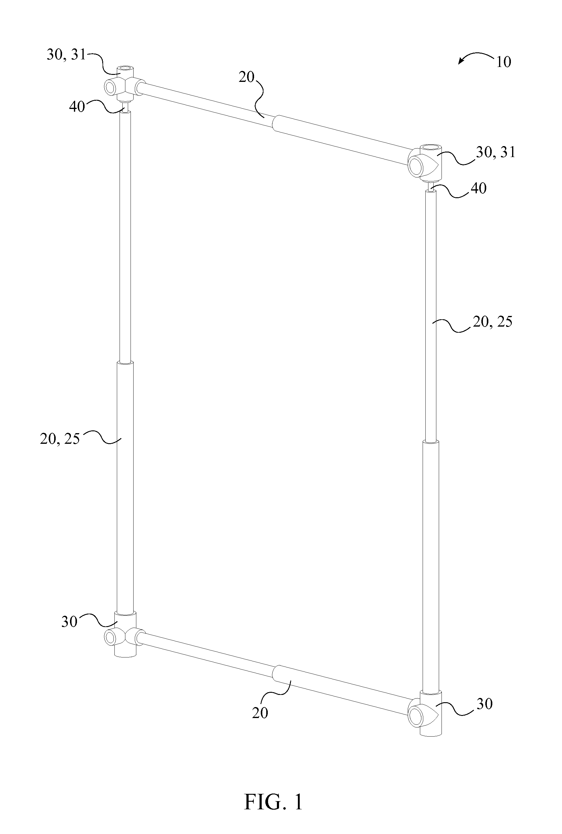
The present invention provides a window rack that can be easily installed without any permanent fasteners. It consists of a plurality of slide members and multi-directional connectors that can be arranged in different ways to fit different sized and shaped windows. The rack has a spring-loaded coupler that compresses the rack to fit into the window frame and securely holds it in place. A window treatment support can be attached to the window rack to create three-dimensional window treatment arrangements. The support can be in different shapes to provide unique window treatment arrangements.

Problems solved by technology

Many hanging mechanisms require the use of screws or nails in order to be installed into the window frame and thus cause permanent damage to the window frame.
The tools needed to install these hanging mechanisms may not be available to or suitable for all individuals.
For example, it may be difficult for the elderly to reach up high while maneuvering tools such as a hammer or screw driver.
Additionally, the permanent nature of many hanging mechanisms limits an individual from changing the way in which window treatments are hung as it is often undesirable to install a second hanging fixture, causing more damage to the window frame.
Thus an individual is usually limited to single hanging fixture.
Hanging mechanisms of this nature are also problematic for individuals living in temporary residencies such as dormitories or apartments.

Method used


Image

  • Spring-Loaded Adjustable Window Rack
  • Spring-Loaded Adjustable Window Rack
  • Spring-Loaded Adjustable Window Rack

Examples


Embodiment Construction

[0017]All illustrations of the drawings are for the purpose of describing selected versions of the present invention and are not intended to limit the scope of the present invention.

[0018]The present invention is a spring-loaded adjustable window rack for supporting and displaying window treatments. The present invention can be quickly assembled and installed into a window frame without the use of any tools. Additionally, the present invention can be utilized as either a temporary or permanent fixture. In the preferred embodiment of the present invention, the components are fabricated from polyvinylchloride, however, it is possible for any other material or materials to be used in the construction of the present invention, with preference given to materials with high strength and being light in weight.

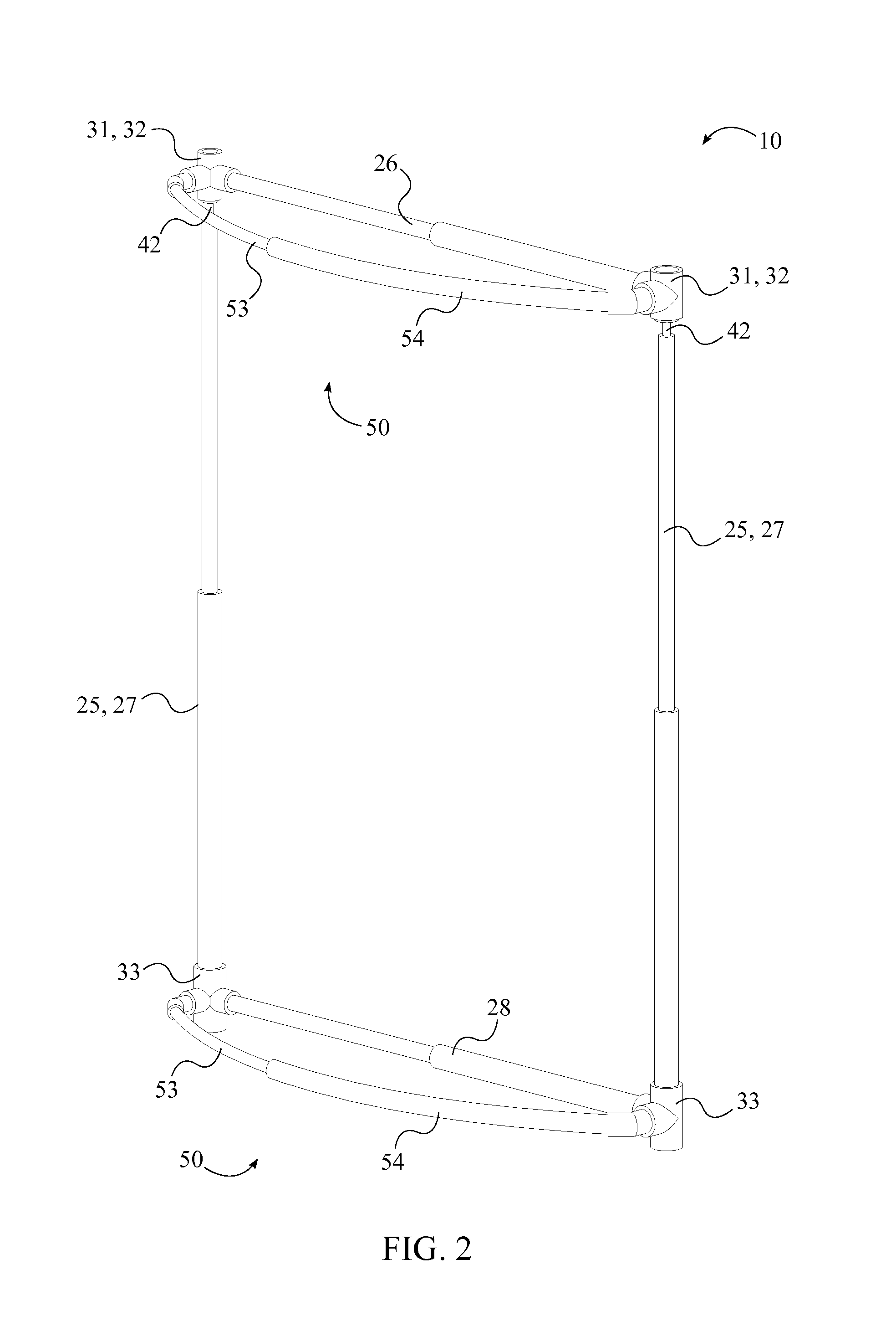
[0019]In reference to FIG. 2, the spring-loaded adjustable window rack comprises a plurality of slide members 20, a plurality of multi-directional connectors, at least one spring-loade...


PUM


Abstract

A spring-loaded adjustable window rack for hanging window treatments. A window rack is formed from a plurality of slide members, a plurality of multi-directional connectors, and at least one spring-loaded coupler, wherein the plurality of slide members is attached to each other by the plurality of multi-directional connectors. Each of the at least one spring-loaded couplers is attached in between a specific connector from the plurality of multi-directional connectors and a corresponding slide member from the plurality of slide members. By compressing the at least one spring the window rack can be slid into a window frame, wherein the spring force holds the window rack in place. A window treatment support can be attached to the window rack for creating three dimensional window treatment arrangements.

Description

[0001]The current application claims a priority to the U.S. Provisional Patent application Ser. No. 61 / 841,265 filed on Jun. 28, 2013.FIELD OF THE INVENTION [0002]The present invention relates generally to window hangings. More specifically, the present invention is a customizable window rack for supporting and displaying window treatments.BACKGROUND OF THE INVENTION [0003]It is common to install window treatments, such as drapes, valances, curtains, and other various hangings, about windows. Such window treatments can be used either entirely for decorative purposes or be used to block out light as well. Typically, these window treatments are not installed directly onto a window frame, but rather are installed through the use of a rod, brackets, hooks, or similar hanging mechanisms. Many hanging mechanisms require the use of screws or nails in order to be installed into the window frame and thus cause permanent damage to the window frame. The tools needed to install these hanging me...

Claims


Application Information

Patent Timeline
IPC IPC(8): A47H1/18
CPCA47H1/18A47H2/00A47H1/022A47H1/122A47H1/142A47H2001/0205A47H2001/0215E06B9/24
Inventor AMOS, JOYCE, C.
Owner AMOS JOYCE C
Learn More