
Structure of Correction Shoe Pad for Medical Purposes

a technology for shoe pads and structures, applied in the direction of uppers, boots, insoles, etc., can solve the problems of sprains or even pain and hurt of knee joints, eversion of soles or ankle ligaments, etc., to prevent inversion and eversion, and prevent eversion of soles. , to improve the stability of standing

Inactive Publication Date: 2015-01-01
JET CROWN INT
View PDF30 Cites 10 Cited by
  • Summary
  • Abstract
  • Description
  • Claims
  • Application Information

AI Technical Summary

Benefits of technology

The present invention provides a correction shoe pad for medical purposes that helps prevent various foot and knee joint disorders. The structure of the shoe pad includes shock-absorbers at different locations in the human sole to provide a balanced and stable support for walking, running, and standing. The shoe pad also reduces impacts from ground vibrations and effectively protects the heel bone and arches from pain and harm. Additionally, the shoe pad takes advantage of a shock-absorber at the outside of the human sole to prevent eversion, ankle sprain, bandy-leg, and wear of knee joints.

Problems solved by technology

During movements, the two feet, particular the foot soles, must bear the body weight and reaction forces from the ground and they often suffer more accumulated fatigue and damage of repeated pressurization resulting from long term standing and walking than other parts of the human body.
This is even more severe in case of the flat feet, high arches, or incorrect arch, which often more readily cause eversion of sole or ankle ligament sprain or even pain and hurt of knee joints.
However, the compound shoe pad disclosed in the previously mentioned Taiwan Utility Model M307982 structurally does not include, at a location corresponding to the lateral arch of the foot sole, a shock-absorber to provide support to the lateral arch so that when a user is walking, standing, running and moving motion, the center of weight of the foot sole will shift outward, leading to eversion or pronation of the outer side of the foot sole.
This may lead to damages such as sole fascia inflammation and ankle ligament sprain and may also affect the legs and knees of the user to cause negative situations, such as bandy legs or improper wear of meniscus of knee joints, as shown in FIG. 4.

Method used


Image

  • Structure of Correction Shoe Pad for Medical Purposes
  • Structure of Correction Shoe Pad for Medical Purposes
  • Structure of Correction Shoe Pad for Medical Purposes

Examples


Embodiment Construction

[0019]The following descriptions are exemplary embodiments only, and are not intended to limit the scope, applicability or configuration of the invention in any way. Rather, the following description provides a convenient illustration for implementing exemplary embodiments of the invention. Various changes to the described embodiments may be made in the function and arrangement of the elements described without departing from the scope of the invention as set forth in the appended claims.

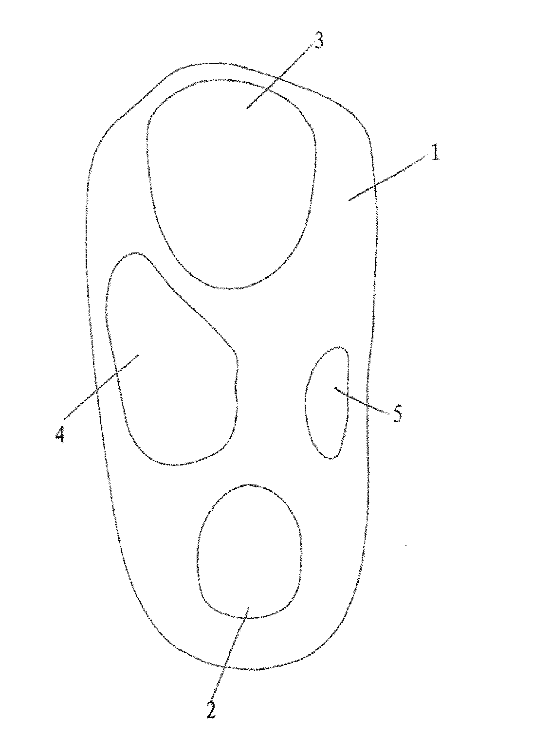
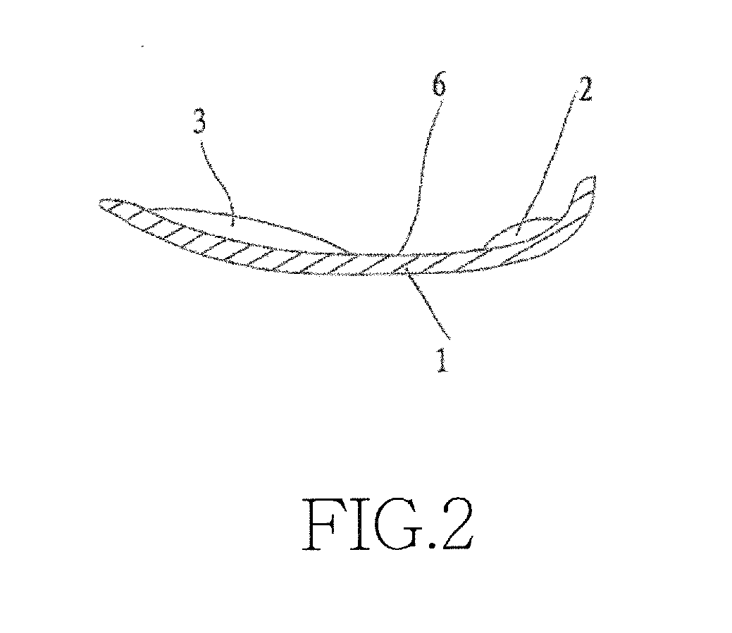
[0020]Referring to FIGS. 1 and 2, a structure of a correction shoe pad for medical purposes according to the present invention generally comprises a pad body (1) having the characteristics of shock absorption and back bouncing. The pad body (1) has a rear portion on which a first shock-absorber (2) that is shock-absorbable and back-bouncing and shows a convex arc configuration is mounted. The pad body (1) has a front portion on which a second shock-absorber (3) that is shock-absorbable and back-boun...


PUM


Abstract

A structure of a correction shoe pad includes a shock-absorber mounted at an outside portion of a pad body of a shoe pad, so that the shock-absorber mounted at the outside portion of the pad body provides support to effectively prevent situations, such as eversion and ankle sprain causing by shift of the center of the body weight of the user toward the outer side of the sole and also to provide effects of bandy leg and wear of meniscus of knee joints resulting from the shift of the center of the body weight of the user toward the outer side of the sole.

Description

TECHNICAL FIELD OF THE INVENTION[0001]The present invention generally relates to a structure of a corrective shoe pads for medical purposes, and more particularly to a structure of a corrective shoe pads for medical purposes having effects of preventing eversion, ankle ligament sprain, bandy-leg, and wear of knee joint.DESCRIPTION OF THE PRIOR ART[0002]Human beings use two feet to stand, walk, run and moving motion. During movements, the two feet, particular the foot soles, must bear the body weight and reaction forces from the ground and they often suffer more accumulated fatigue and damage of repeated pressurization resulting from long term standing and walking than other parts of the human body. This is even more severe in case of the flat feet, high arches, or incorrect arch, which often more readily cause eversion of sole or ankle ligament sprain or even pain and hurt of knee joints.[0003]To overcome such problems, manufacturers have developed and provided the shoe pads that he...

Claims


Application Information

Patent Timeline
IPC IPC(8): A43B13/38A43B7/14A43B7/32A43B13/40
CPCA43B7/14A43B7/32A43B13/38A43B13/40A43B7/142A43B7/143A43B7/144A43B7/1445A43B7/149A43B17/02
Inventor WANG, EDMUND
Owner JET CROWN INT
Learn More