
Recording substrate treatment apparatus, printing system and method of drying

a technology of recording substrate and treatment apparatus, which is applied in the direction of printing and other printing apparatus, can solve the problems of deteriorating drying capacity of recording substrate treatment apparatus, energy loss, and build-up of vaporous components in the circulating gaseous medium, and achieve the effect of large drying capacity

Active Publication Date: 2014-12-25
OCE TECH
View PDF2 Cites 7 Cited by
  • Summary
  • Abstract
  • Description
  • Claims
  • Application Information

AI Technical Summary

Benefits of technology

This patent describes a treatment apparatus for recording substrates that is suitable for high-speed printers or printing systems with large drying capacity. The apparatus is also energy-efficient.

Problems solved by technology

The resulting suction flow where no recording substrate is present may have an unwanted cooling effect on the transportation mechanism, leading to energy loss.
However, when recirculating the suction flow (of a gaseous medium, in particular air) build-up of vaporous components in the circulating gaseous medium and originating from the printing substance may occur.
Hence, the drying capacity of the recording substrate treatment apparatus deteriorates.
Removing such vaporous components requires cooling of the circulating gaseous medium in order to condensate the vaporous components, which again causes an energy loss.
It is a disadvantage of recording substrate treatment apparatuses known from the background art that the printed recording substrates are solely dried with a flow of a heated gaseous medium, which is an indirect method of heating.
Such recording substrate treatment apparatuses are not suitable for use in a highly productive printer, because of the limited drying capacity of such recording substrate treatment apparatuses.
It is another disadvantage that the entire circulating flow of the gaseous medium needs to be cooled down to remove vaporous components, which is energy inefficient.
It is a disadvantage of the printing apparatus disclosed in U.S. Application Publication No. 2005 / 0092200, because it provides a relatively slow heating method, which is less suitably applied in highly productive printers or printing systems

Method used


Image

  • Recording substrate treatment apparatus, printing system and method of drying
  • Recording substrate treatment apparatus, printing system and method of drying
  • Recording substrate treatment apparatus, printing system and method of drying

Examples


Embodiment Construction

[0088]The present invention will now be described with reference to the accompanying drawings wherein the same or similar elements have been identified with the same reference numerals.

Printing Process

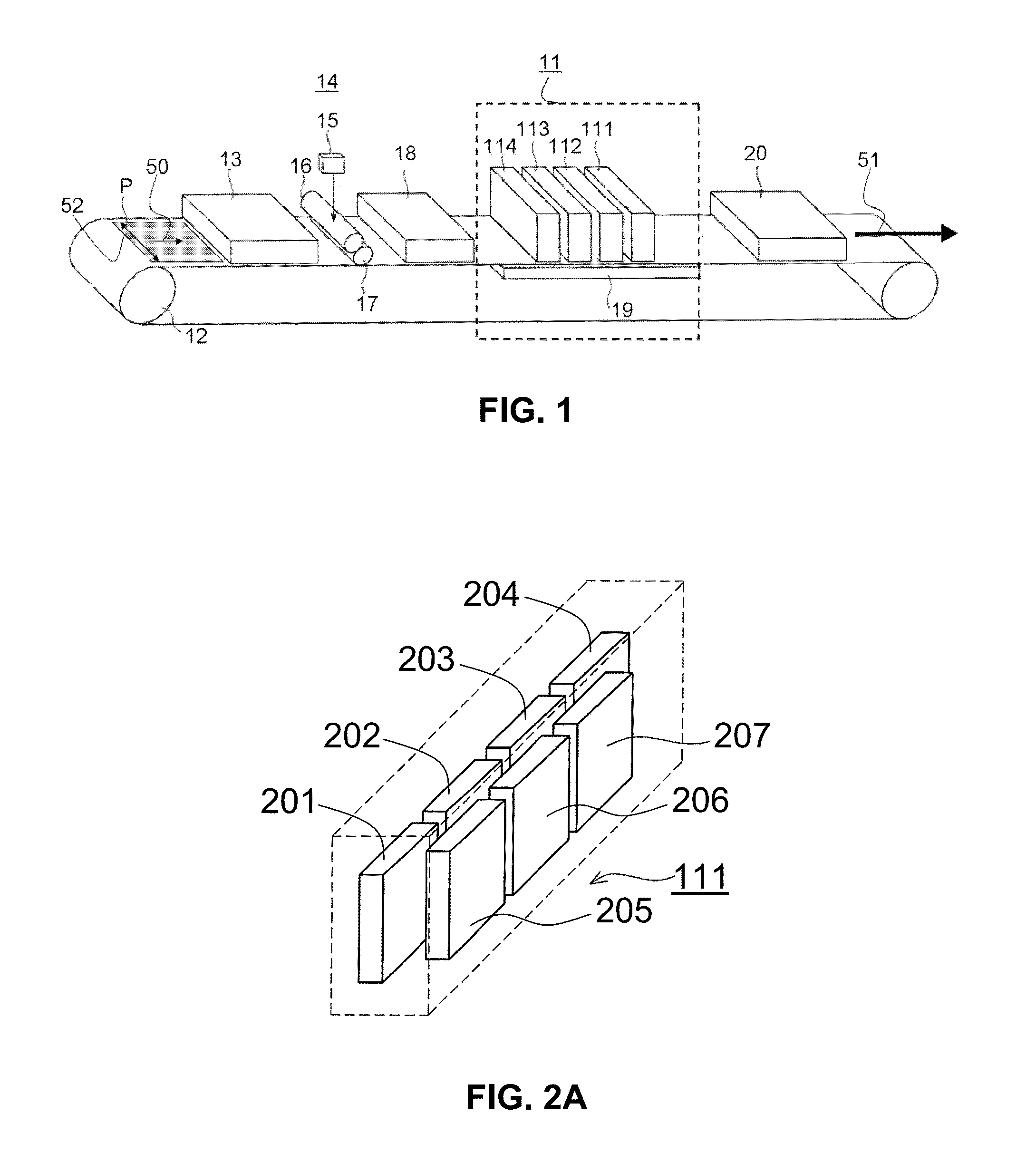
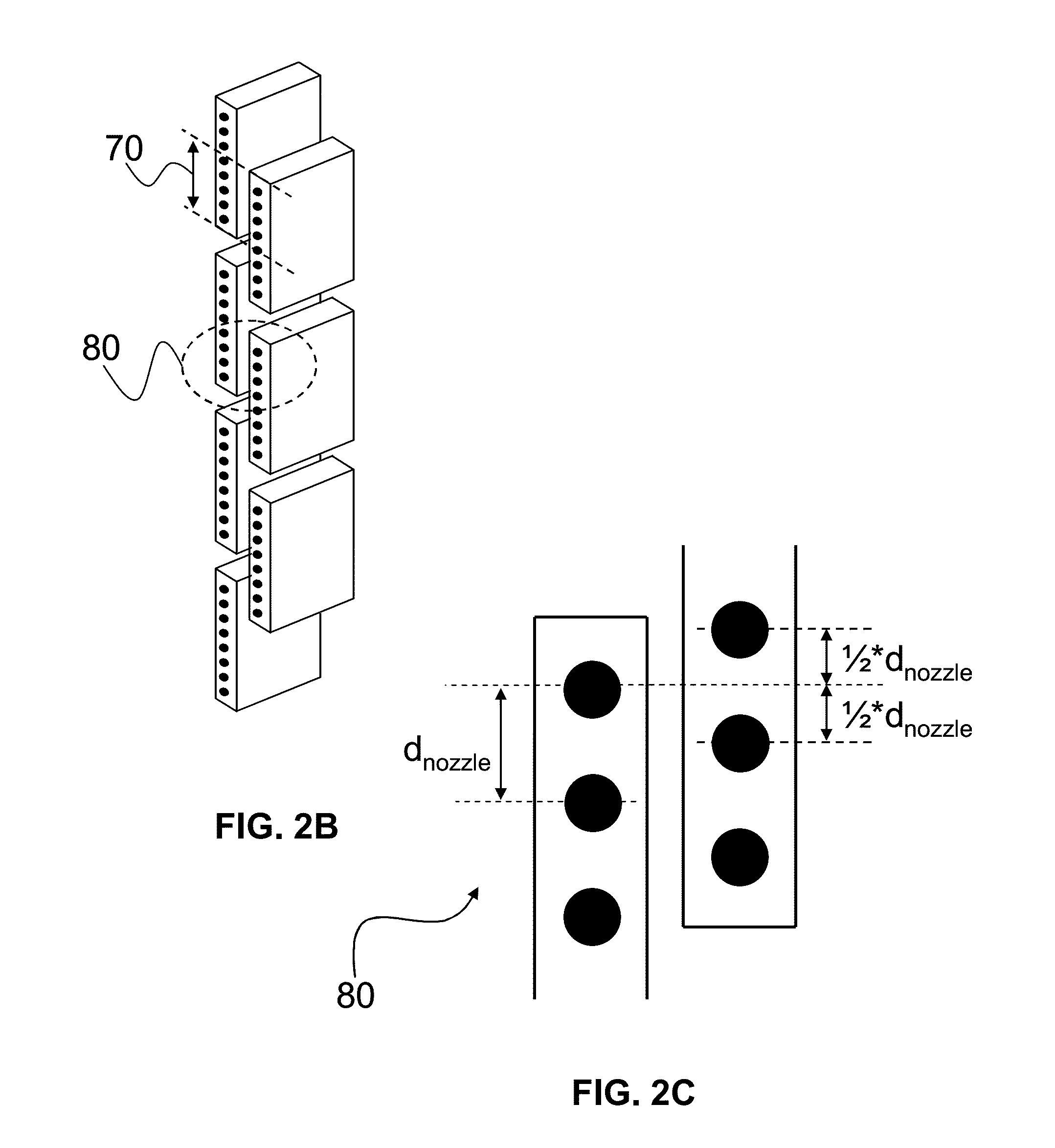
[0089]A printing process in which the inks according to the present invention may be suitably used is described with reference to the appended drawings shown in FIG. 1 and FIG. 2. FIGS. 1 and 2 are schematic representations of an inkjet printing system and an inkjet marking device, respectively.

[0090]FIG. 1 shows that a sheet of a receiving medium, in particular a machine coated medium, P, is transported in a direction for conveyance as indicated by arrows 50 and 51 and with the aid of transportation mechanism 12. Transportation mechanism 12 may be a driven belt system comprising one (as shown in FIG. 1) or more belts. Alternatively, one or more of these belts may be exchanged for one or more drums. A transportation mechanism may be suitably configured depending on the requirements (e....


PUM


Abstract

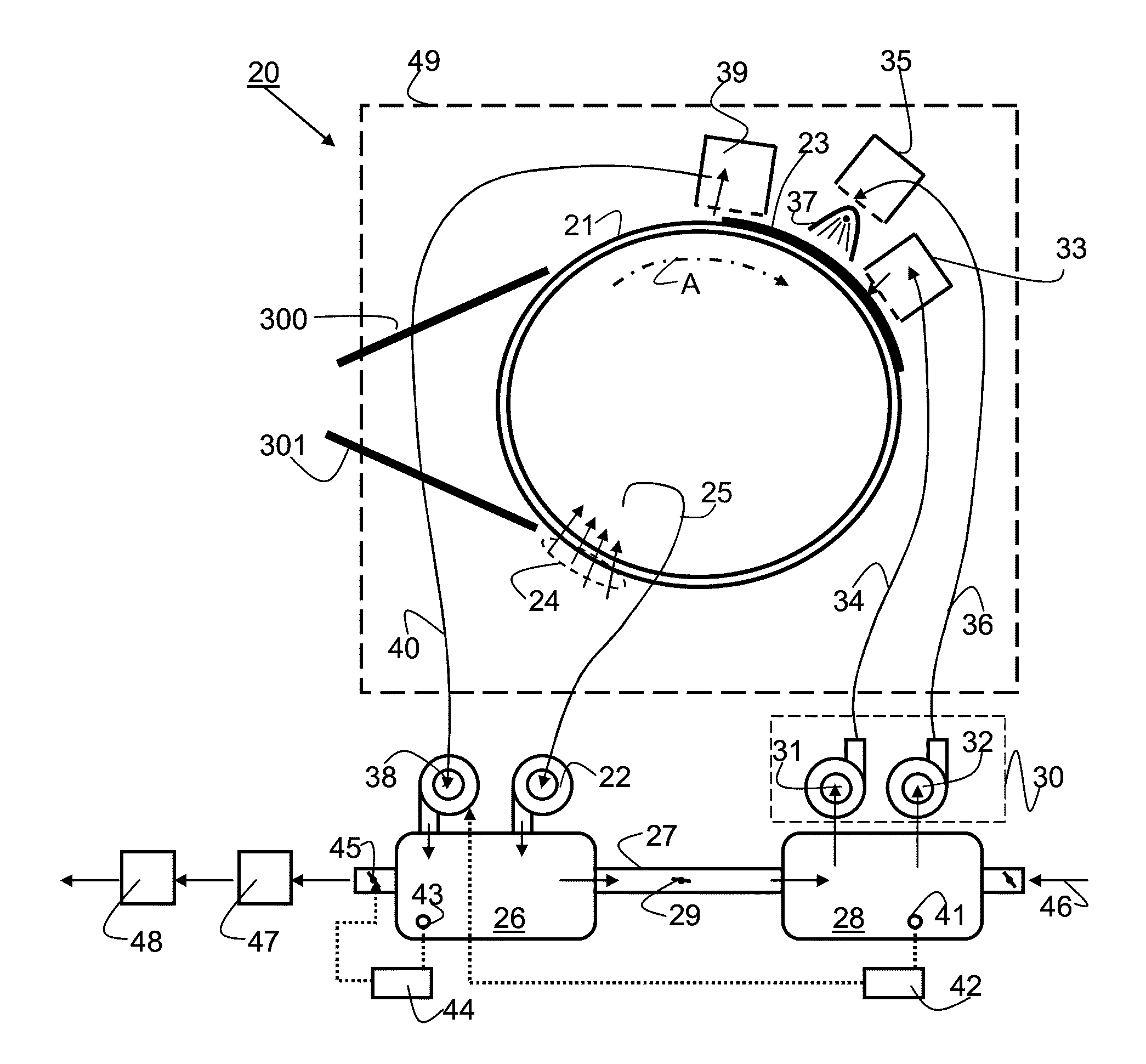
A recording substrate treatment apparatus includes a transporting mechanism for transporting a sheet of a recording substrate; a suction device to provide an underpressure force at an outer surface of the transporting mechanism arranged for holding down a sheet of a recording substrate; a heater for directly heating the recording substrate; and a blower for providing a flow of a gaseous medium at the outer surface of the transporting mechanism, wherein in operation the blower receives the gaseous medium from the suction device. The present invention also pertains to a printing system comprising such a recording substrate treatment apparatus and a method of drying a recording substrate using such a recording substrate recording apparatus.

Description

CROSS-REFERENCE TO RELATED APPLICATIONS[0001]This application is a Continuation of International Application No. PCT / EP2013 / 053425, filed on Feb. 21, 2013, and for which priority is claimed under 35 U.S.C. §120. PCT / EP2013 / 053425 claims priority under 35 U.S.C. §119(a) to Application No. 12158187.0, filed in Europe on Mar. 6, 2012. The entire contents of each of the above-identified applications are hereby incorporated by reference into the present application.BACKGROUND OF THE INVENTION[0002]1. Field of the Invention[0003]The present invention relates to a recording substrate treatment apparatus, in particular a recording substrate treatment apparatus for a printer or copier. For example, the recording substrate treatment apparatus comprises at least one of a drying device for drying a re-cording substrate and a fixing device for fixing a printing substance on a recording substrate. For example, the fixing device may be or comprise a fuser. The present invention further relates to ...

Claims


Application Information

Patent Timeline
Patent Type & Authority Applications(United States)
IPC IPC(8): B41J11/00B41J2/01
CPCB41J2/01B41J11/002B41J11/0085B41J11/00214B41J11/0022
Inventor VAN BEEK, ALBERT M.HOLLANDS, PETER J.
Owner OCE TECH
Learn More