
Rope for lifting and an elevator comprising the rope

a technology for elevators and ropes, applied in the field of ropes, can solve the problems of poor fretting performance and reduced life time, and achieve the effects of reducing the fretting of ropes, and shortening the life time of metal ropes

Inactive Publication Date: 2014-12-25
NV BEKAERT SA
View PDF0 Cites 11 Cited by
  • Summary
  • Abstract
  • Description
  • Claims
  • Application Information

AI Technical Summary

Benefits of technology

The present invention provides a metal rope with a three-layered structure that reduces the critical spot on the rope where the load is concentrated, resulting in a more even distribution of the load among the strands and an increased lifespan. By carefully selecting the number of inner and outer strands, the frequency of filament alignment can be avoided, reducing the likelihood of fretting and resulting in a longer life for the rope. The invention can also further decrease the amount of fretting and increase the life of the rope through other measures such as increasing the size of the metal rope, adding a protective cover, and reducing tension on the rope.

Problems solved by technology

The rope performs well on strength and corrosion resistance, but it has a poor performance on fretting.
However, experience has shown that this cord may show fretting along some of its steel filaments with a reduced life time as a negative result.

Method used


Image

  • Rope for lifting and an elevator comprising the rope
  • Rope for lifting and an elevator comprising the rope
  • Rope for lifting and an elevator comprising the rope

Examples


first embodiment

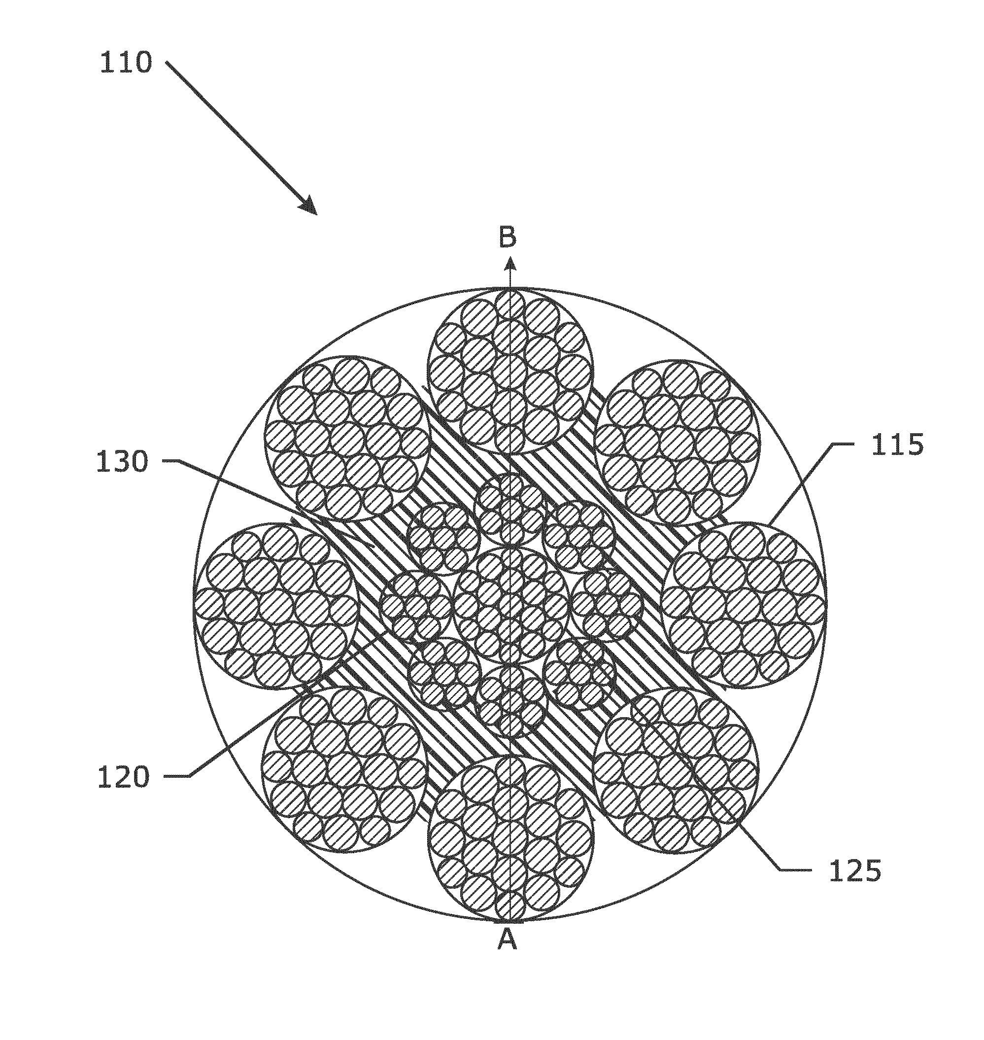
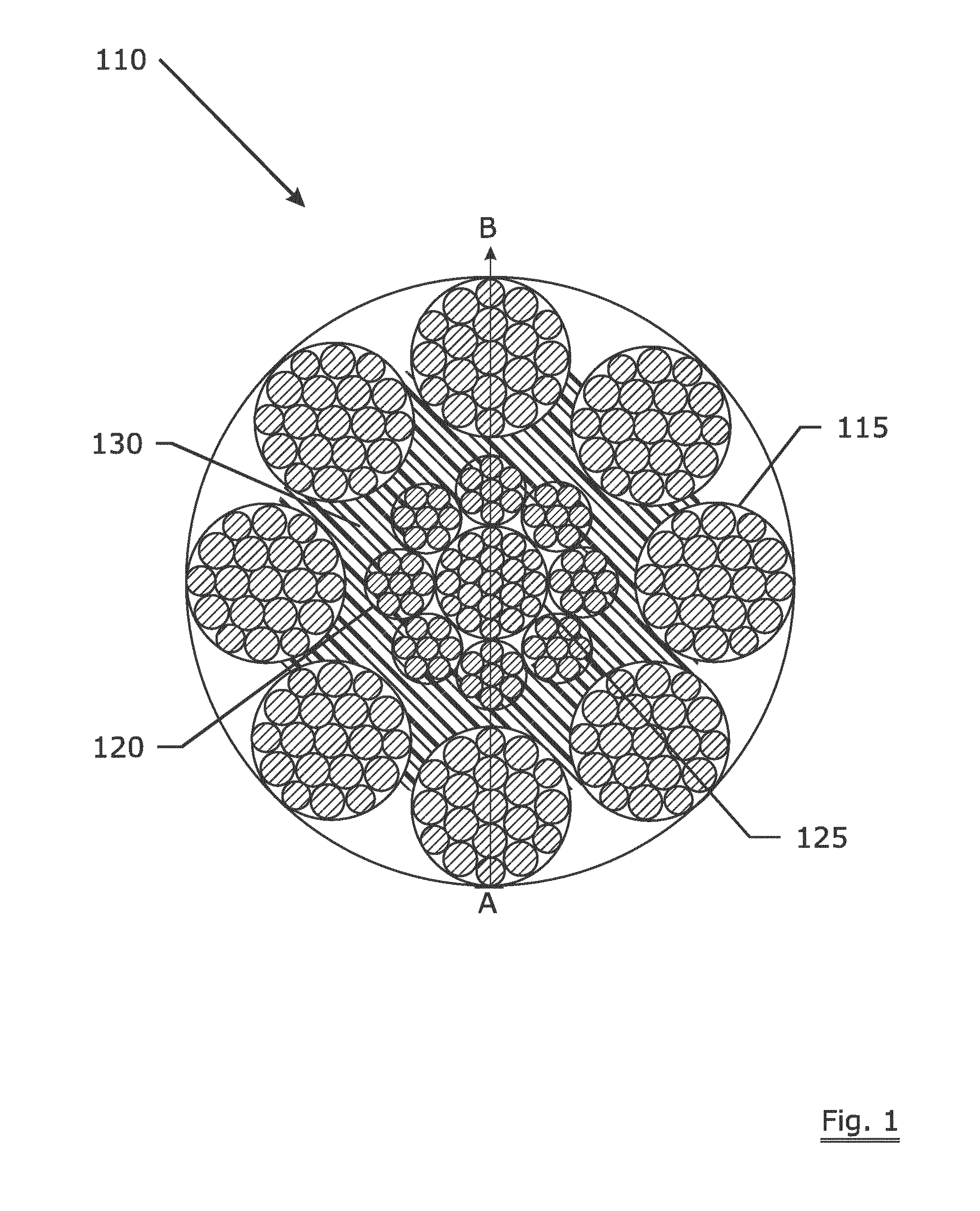
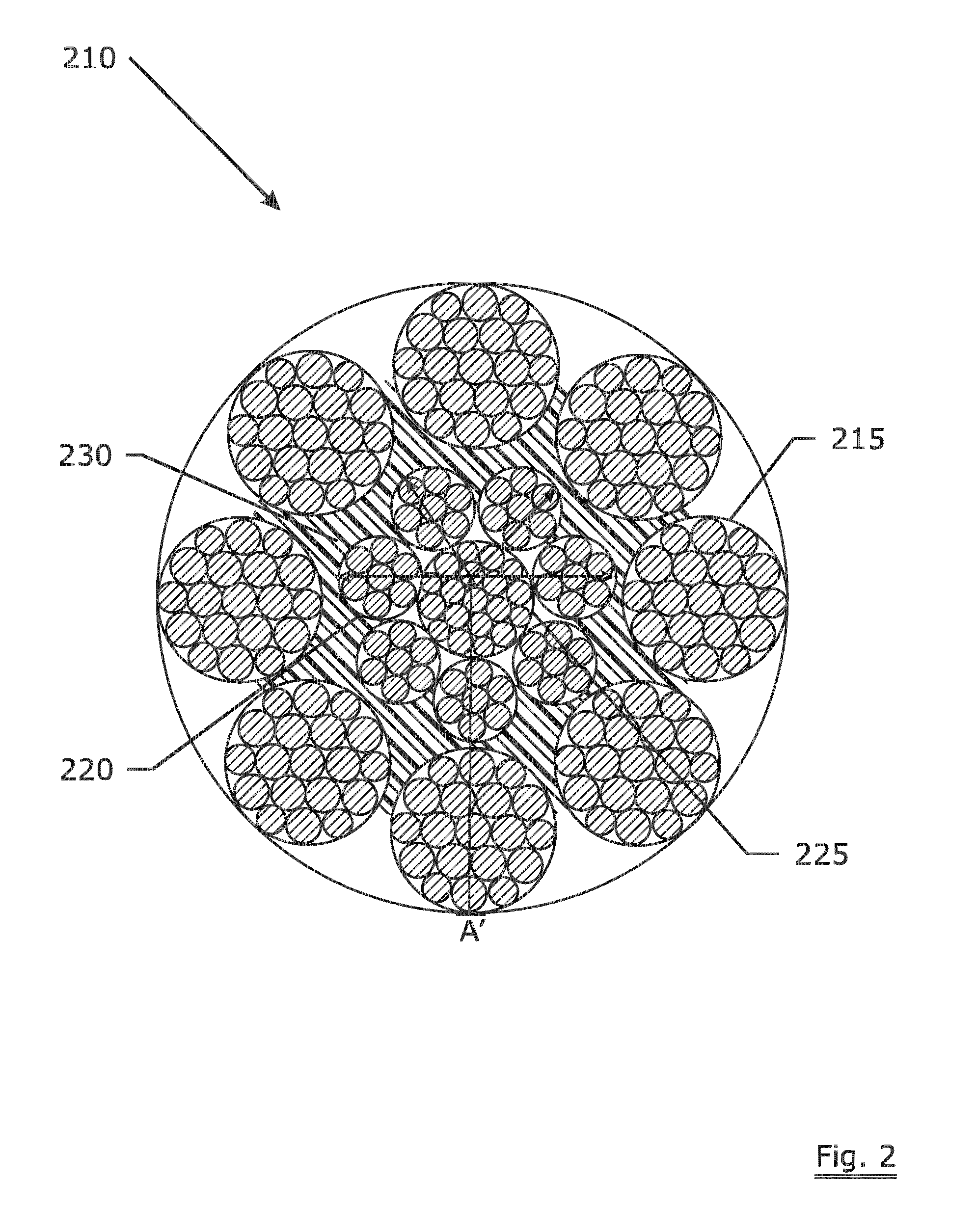
[0036]FIG. 2 illustrates the present invention. The steel rope 210 has a core layer, an inner layer and an outer layer. The core layer comprises one strand 225 which is a Warrington strand having a structure of 1+6+12. The inner layer has 7 strands 220 with a structure of 1+6. The outer layer has 8 strands 215 with a structure of 1+6+12. The steel filaments in the strand have a carbon content of 0.70%. The steel rope has a PU layer 230 surrounding the inner layer. While applying the rope 110 on the pulley in a lifting system, the spot A′ of the rope 210 is the contact point between the rope 210 and the pulley. No filaments get aligned in everywhere along the length of the rope.

[0037]Compared with the prior-art rope 110, the load distribution from the spot A′ to the other side of the rope 210 isn't in a line, instead of only a few filaments carrying the load, more filaments in the rope 210 carry the load. This avoids the ‘filaments alignment phenomenon’ and reduces the fretting of th...

second embodiment

[0040]FIG. 3 illustrates the present invention. The steel rope 310 has a core layer, an inner layer and an outer layer. The core layer comprises one strand 315 which has a structure of 1+6, the inner layer has 5 strands 220 and the outer layer has 7 strands 215. The rope 310 has a PU layer 325 surrounding the outer layer and a PE layer 320 surrounding the inner layer.

third embodiment

[0041]A third embodiment is a steel rope having a core layer comprising one strand with a structure of 1+6, an inner layer comprising 7 strands with a structure of 1+8 and an outer layer comprising 18 strands with a structure of 1+6+12.


PUM

PropertyMeasurementUnit
lengthaaaaaaaaaa
diametersaaaaaaaaaa
strengthaaaaaaaaaa

Abstract

A rope (210, 310) having a three-layered structure comprising a core layer, an inner layer and an outer layer, the core layer comprising one strand (225, 315), the inner layer comprising multiple strands (220) with an amount n and the outer layer comprising multiple strands (215) with an amount m, wherein n is an uneven number, and m is a number which has no common divisor with n, each strand is formed by multiple twisted metal filaments. By this structure fretting of the strands is reduced and the life time of the rope is improved. Also, the use of the rope in lifting application and an elevator system comprising such a rope are disclosed.

Description

TECHNICAL FIELD[0001]The present invention relates to a rope. The rope comprises a core layer, an inner layer and an outer layer. The core layer comprises one strand, the inner layer comprises multiple strands and the outer layer comprises also multiple strands. The invention also relates to the application of such a rope in an elevator system and to an elevator system with such a rope.BACKGROUND ART[0002]Multi-strand cords are well known in the general art of steel ropes and in the particular art of lifting.[0003]US20080314016 discloses a rope for hoisting application. The rope performs well on strength and corrosion resistance, but it has a poor performance on fretting.[0004]Another example of such a multi-strand rope is 1×19+8×7+8×19. This rope has proven its merits in the art of lifting. However, experience has shown that this cord may show fretting along some of its steel filaments with a reduced life time as a negative result.DISCLOSURE OF INVENTION[0005]It is an object of the...

Claims


Application Information

Patent Timeline
Patent Type & Authority Applications(United States)
IPC IPC(8): D07B1/06B66B7/06B66B9/00
CPCD07B1/0633B66B7/06B66B9/00D07B1/0666D07B1/0606D07B1/0673D07B1/162D07B1/165D07B2201/1012D07B2201/102D07B2201/1036D07B2201/1072D07B2201/108D07B2201/2061D07B2201/2065D07B2201/2073D07B2201/2074D07B2201/2087D07B2205/2003D07B2205/201D07B2205/2064D07B2401/207D07B2501/2007D07B2501/2015D07B2801/24D07B2801/16D07B2801/20D07B2801/22
Inventor DECONINCK, JANROMMEL, HENDRIKKLUST, ANDREASLEFEBVRE, DOMINIQUE
Owner NV BEKAERT SA
Learn More