
Graphic self-diagnostic system and method

a self-diagnostic system and self-diagnostic technology, applied in the field of self-diagnostic technologies, can solve the problems of high cost to send the field engineer, user inability to determine the point of failure and troubleshoot accordingly, and parts requiring self-diagnostic are typically fault-prone and vulnerable. , to achieve the effect of reducing the related maintenance cost, reducing the shut-down time, and easy identification of the specific failed par

Inactive Publication Date: 2014-12-18
GE MEDICAL SYST GLOBAL TECH CO LLC
View PDF20 Cites 3 Cited by
  • Summary
  • Abstract
  • Description
  • Claims
  • Application Information

AI Technical Summary

Benefits of technology

The invention provides a simple solution for field failure diagnostics, which helps in identifying the specific failed part easily and reducing maintenance cost and shut-down time. The system allows engineers to determine whether they should go in person or carry new parts to the site to replace the failed parts, thus reducing the number of round trips and time for engineers, and saving the cost. The self-diagnostic system can be used in equipment, machines, systems, or devices, making it more readily available for users and vendors. Overall, the invention improves the efficiency and reliability of equipment, machines, and systems.

Problems solved by technology

If this equipment is deployed in remote rural regions, cost will be very high to send the field engineer.
The parts requiring self-diagnostic are typically fault-prone and vulnerable; these vulnerable parts are often critical parts.
However, since large-scale equipment often includes complex structures, and a user who uses such equipment often has no specialized knowledge of the relevant equipment construction, even if a self-diagnostic system identifies the cause of the failure and issues an alarm, the user cannot determine the point of failure and troubleshoot accordingly.
In fact, this does not take full advantage of a self-diagnostic system.
When equipment fails, the maintenance cost remains high and it will take a relatively long time to resume the normal operation of the equipment.

Method used


Image

  • Graphic self-diagnostic system and method
  • Graphic self-diagnostic system and method
  • Graphic self-diagnostic system and method

Examples


Embodiment Construction

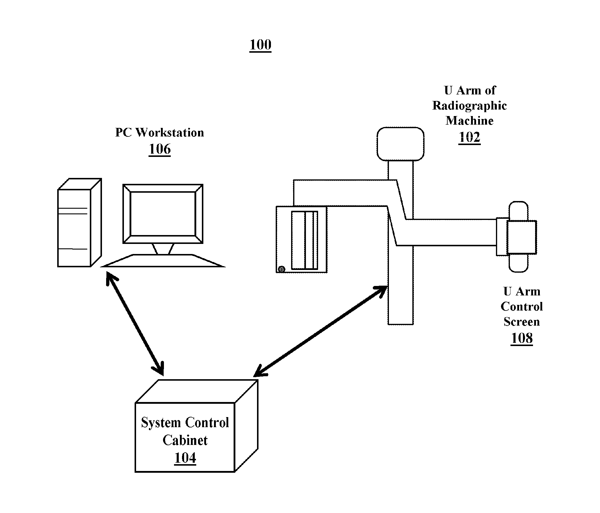
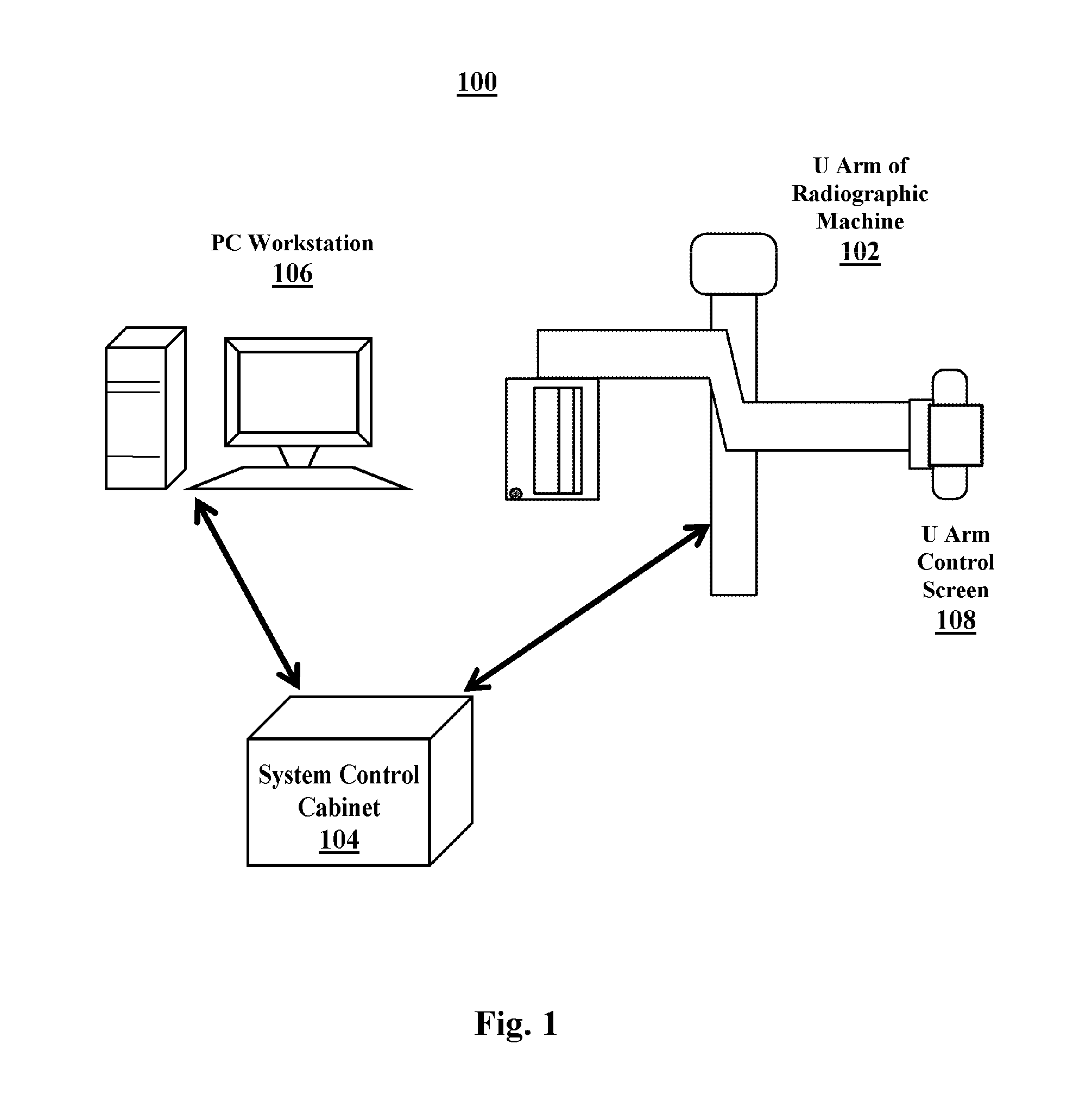
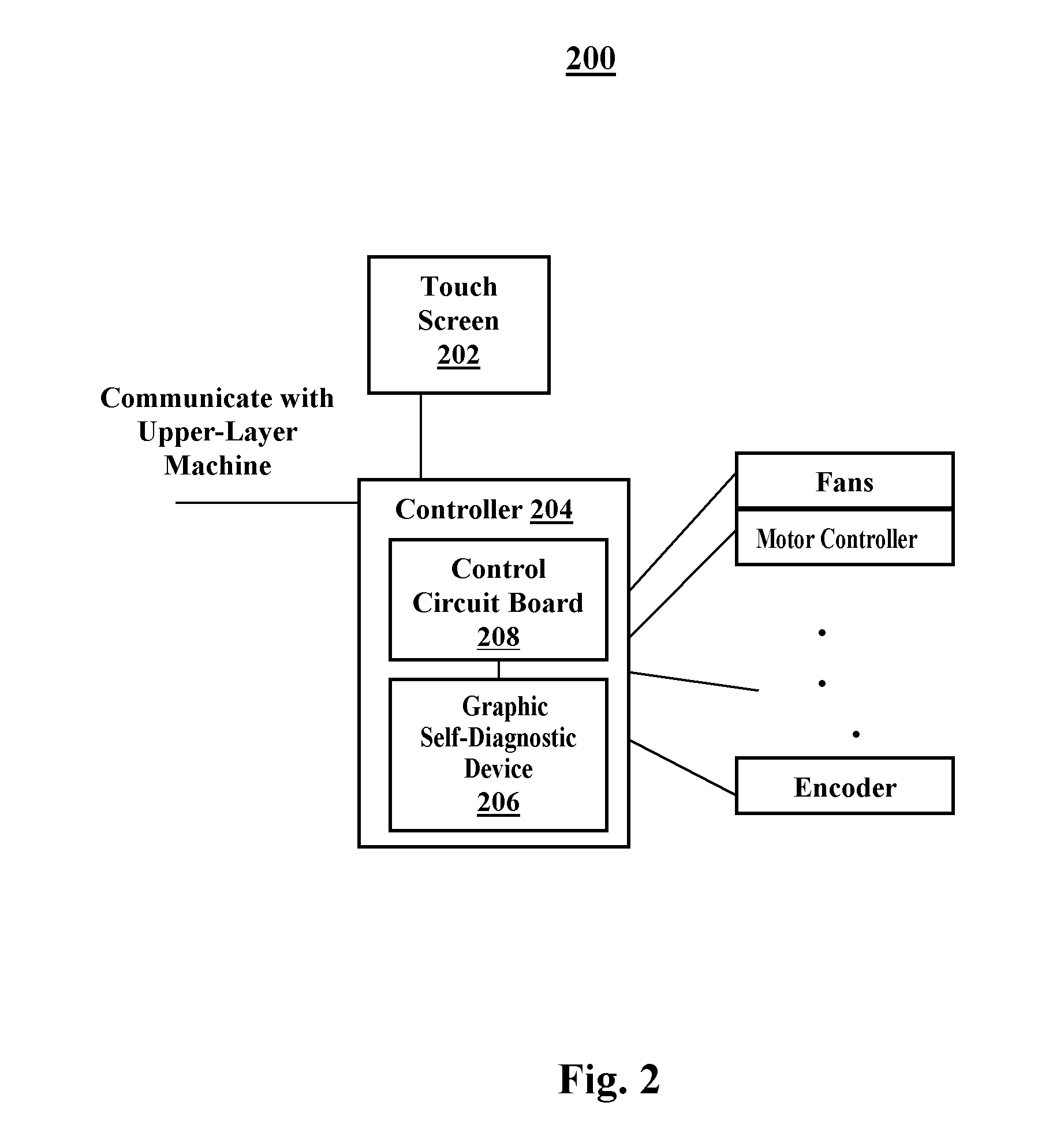
[0047]In the following, the present invention will be described in more detail with reference to illustrative embodiments and to accompanying drawings. For purposes of explanation and not limitation, specific details are set forth, such as particular systems, structures and techniques, etc., in order to enable those skilled in the art to readily understand the present invention. However, it will be apparent to those skilled in the art that the present invention may be practiced in other embodiments without these specific details described herein.

[0048]Those skilled in the art will readily appreciate that all or some of various parts of the system and / or various steps of the method described herein may be implemented in hardware, software and / or firmware. The present invention is not limited to any specific combination of hardware and software.

[0049]Furthermore, while the present invention is primarily described in the form of systems and methods, the present invention may also be em...


PUM


Abstract

A graphic self-diagnostic system comprises an input device for inputting a self-diagnostic request and rendering a request of a user; a graphic self-diagnostic device, comprising a failure database module, a failure scan module and a rendering module, for diagnosing one or more parts of the equipment being diagnosed and for generating the graphic diagnostic result; and an output device for outputting the graphic diagnostic result.

Description

TECHNICAL FIELD[0001]Embodiments of the present invention relate generally to the field of self-diagnostic technologies, in particular, to a graphic self-diagnostic system and corresponding method.BACKGROUND ART[0002]When various pieces of equipment, particularly complex equipment (e.g., X-ray equipment, CT equipment and magnetic resonance equipment) fail, field diagnostics of this equipment usually requires well-trained field engineers on site. If this equipment is deployed in remote rural regions, cost will be very high to send the field engineer.[0003]To solve these problems, equipment can be equipped with self-diagnostic systems, which diagnosis the causes of the equipment's failure. For example, a Vision VDIX140 radiographic machine has a self-diagnostic function; many CT machines or magnetic resonance machines may also include a self-diagnostic function; and even f conventional equipment such as a personal computer (PC) may also have self-diagnostic functions that can self-dia...

Claims


Application Information

Patent Timeline
Patent Type & Authority Applications(United States)
IPC IPC(8): G06F11/07
CPCG06F11/079G05B23/0267G06Q10/20
Inventor DU, HAITAOMA, SHUNYAO
Owner GE MEDICAL SYST GLOBAL TECH CO LLC
Learn More