Method and apparatus for determining object characteristics

Active Publication Date: 2014-12-18
PHASE FOCUS
View PDF4 Cites 39 Cited by
  • Summary
  • Abstract
  • Description
  • Claims
  • Application Information

AI Technical Summary

Benefits of technology

This patent is about methods and devices used to determine the thickness or refractive power of an object, specifically a transparent object that has a phase structure or at least partially reflective object. The invention can be used to measure the properties of such objects.

Problems solved by technology

However prior art methods often have drawbacks such as a requirement to be performed by a skilled user, and / or the lens to be removed from a native saline environment for measurement.

Method used

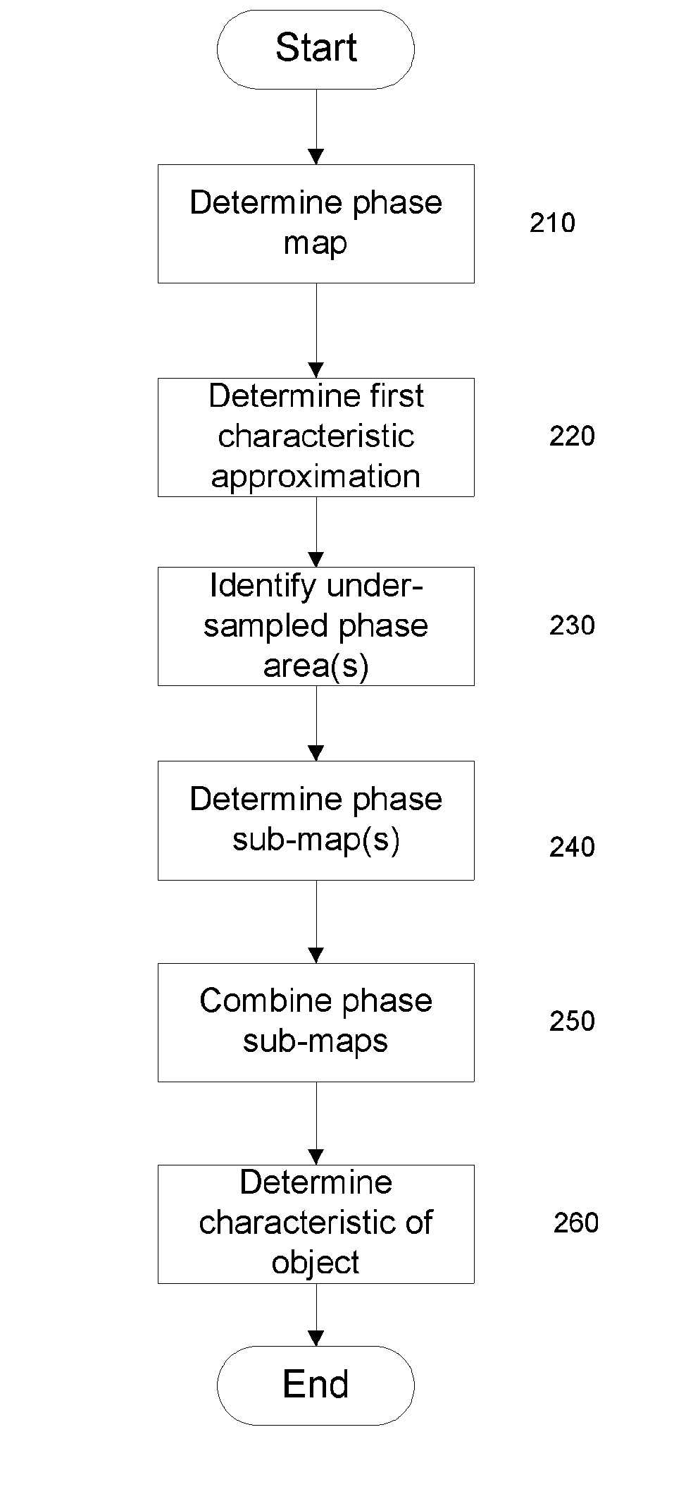
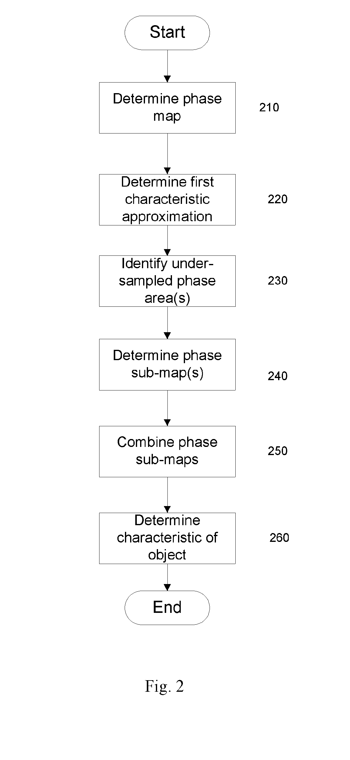

Image

  • Method and apparatus for determining object characteristics
  • Method and apparatus for determining object characteristics
  • Method and apparatus for determining object characteristics

Examples


first embodiment

[0101]In step 970 the power of the lens in air is calculated according to, for example, Optom Vis Sci. 2008 September; 85(9) using Equations 11 and 12:

c1=Pwet+(n2-n1)c2n2-n1+(dn2)c2(n2-n1)2Eqn.11Pair=(n2-1)(c1-c2)+(dn2)c2(n2-n1)2Eqn.12

[0102]Where n1 is the refractive index of the saline, n2 is the refractive index of the lens, d is the centre thickness and c2 is 1 / (lens base curve radius). Pwet is the power in the liquid medium, such as saline, and Pair is the power in air.

second embodiment

[0103]In step 970 the power in air is calculated based upon a virtual position of the lens in the liquid medium resulting from refraction of light rays at the air-liquid interface.

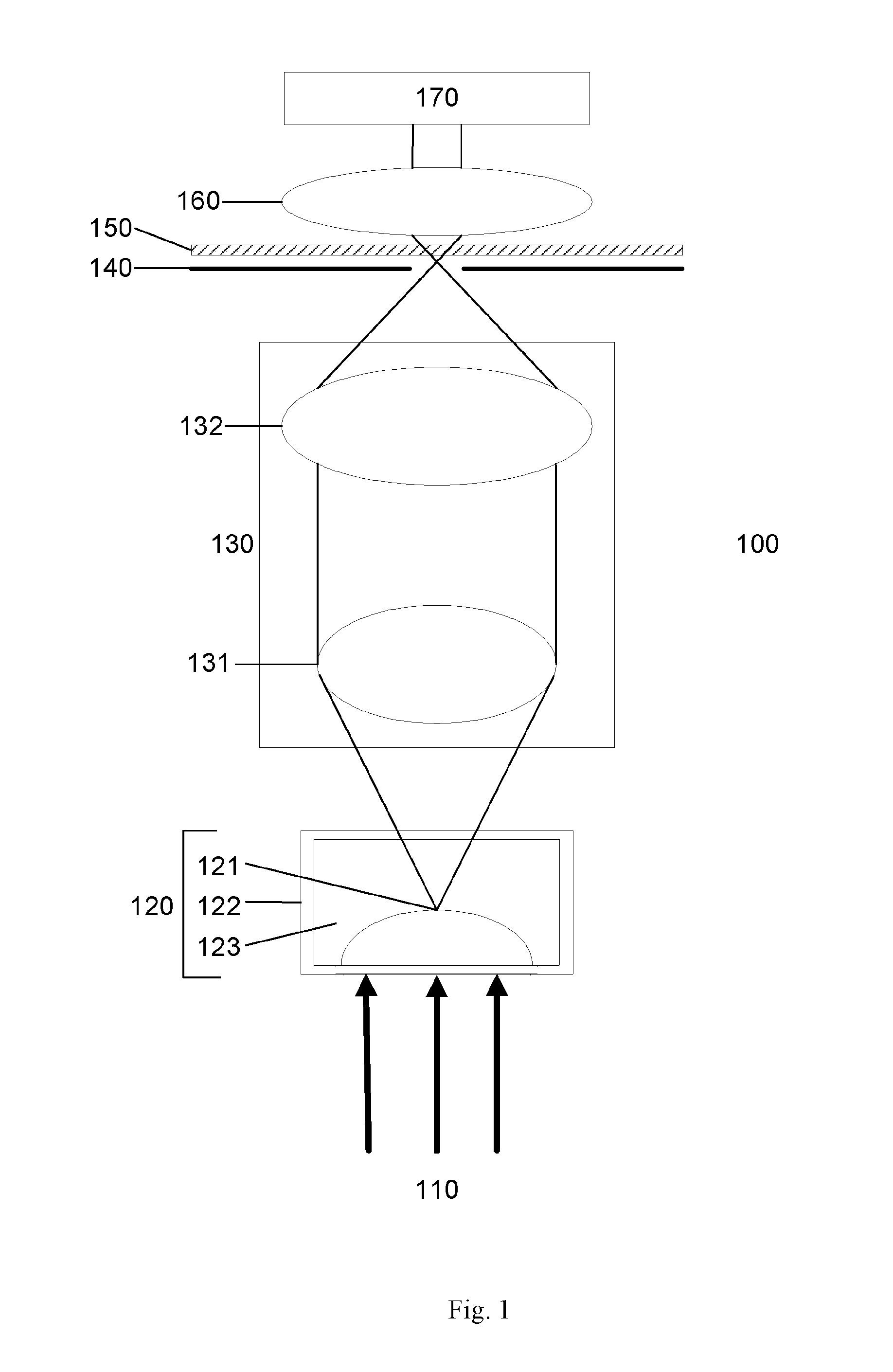
[0104]FIG. 10 illustrates a path 980 of light leaving the actual position of the lens 121 in the saline solution 123. As can be appreciated, refraction occurring at the saline-air interface causes a change in the path 980 of light leaving the lens 121. A measured focal length 991 would thus correspond to a virtual lens 990 at a different location to a focal length 992 completely in the saline solution. Based on the differing intersection angles α, β of the light rays the power of the lens 121 in air may be calculated by Equations 13 and 14 as:

tan(β)=rfsaline=rPsalineEqn.13tan(α)=rfmeasured=rPmeasuredEqn.14

[0105]Where r is a distance between the optical axis and a point on the lens 121, Pmeasured is a measured optical power, Psaline is a power in saline solution (or other liquid medium), fmeasured is a meas...


PUM


Abstract

Embodiments of the invention provide a method of determining one or more characteristics of a target object, comprising determining a first phase map for at least a region of a target object based on radiation directed toward the target object, determining one or more further phase maps for a sub-region of the region of the target object, determining a number of phase wraps for the sub-region based on a plurality of phase maps for the sub-region, and determining a characteristic of the region of the target object based on the number of phase wraps for sub-region and the first phase map. Embodiments of the invention also relate to a method of determining one or more characteristics of a target object, comprising determining a phase map for at least a region of a target object based on one or more diffraction patterns, determining a wavefront at a plane of the object based upon the phase map, and determining a refractive property of the object based on the wavefront.

Description

[0001]Embodiments of the present invention relate to methods and apparatus for determining one or more characteristics of an object.BACKGROUND[0002]It is often desired to determine one or more characteristics of an object. An example of an object for which it may be desired to determine the characteristics is a contact lens. It is often desired to determine one or more characteristics of the contact lens, such thickness and / or optical power of the contact lens. Thickness measurements are often made using a contact measuring device such as a Rehder-style dial gauge or following an invasive procedure performed on the lens, such as sectioning. However prior art methods often have drawbacks such as a requirement to be performed by a skilled user, and / or the lens to be removed from a native saline environment for measurement.[0003]It is an object of embodiments of the invention to at least mitigate one or more of the problems of the prior art.SUMMARY OF THE INVENTION[0004]In particular, ...

Claims


Application Information

Patent Timeline
IPC IPC(8): G01M11/02G01B11/06G01N21/41
CPCG01M11/0235G01N2201/12G01B11/06G01N21/41G01M11/025G01M11/0228G01B11/0633G01B11/24G01M11/08
Inventor HUMPHRY, MARTIN JAMESLANGLEY, KEVINRUSSELL, JAMESMAIDEN, ANDREW MICHAEL
Owner PHASE FOCUS
Why Eureka
Try Eureka