
In-vehicle display apparatus and program product

a technology for vehicle display and program products, applied in static indicating devices, instruments, transportation and packaging, etc., can solve problems such as affecting the understanding of information necessary for driving, reducing the visibility of displayed pictures, and not allowing drivers to be promp

Active Publication Date: 2014-12-18
DENSO CORP
View PDF8 Cites 28 Cited by
  • Summary
  • Abstract
  • Description
  • Claims
  • Application Information

AI Technical Summary

Benefits of technology

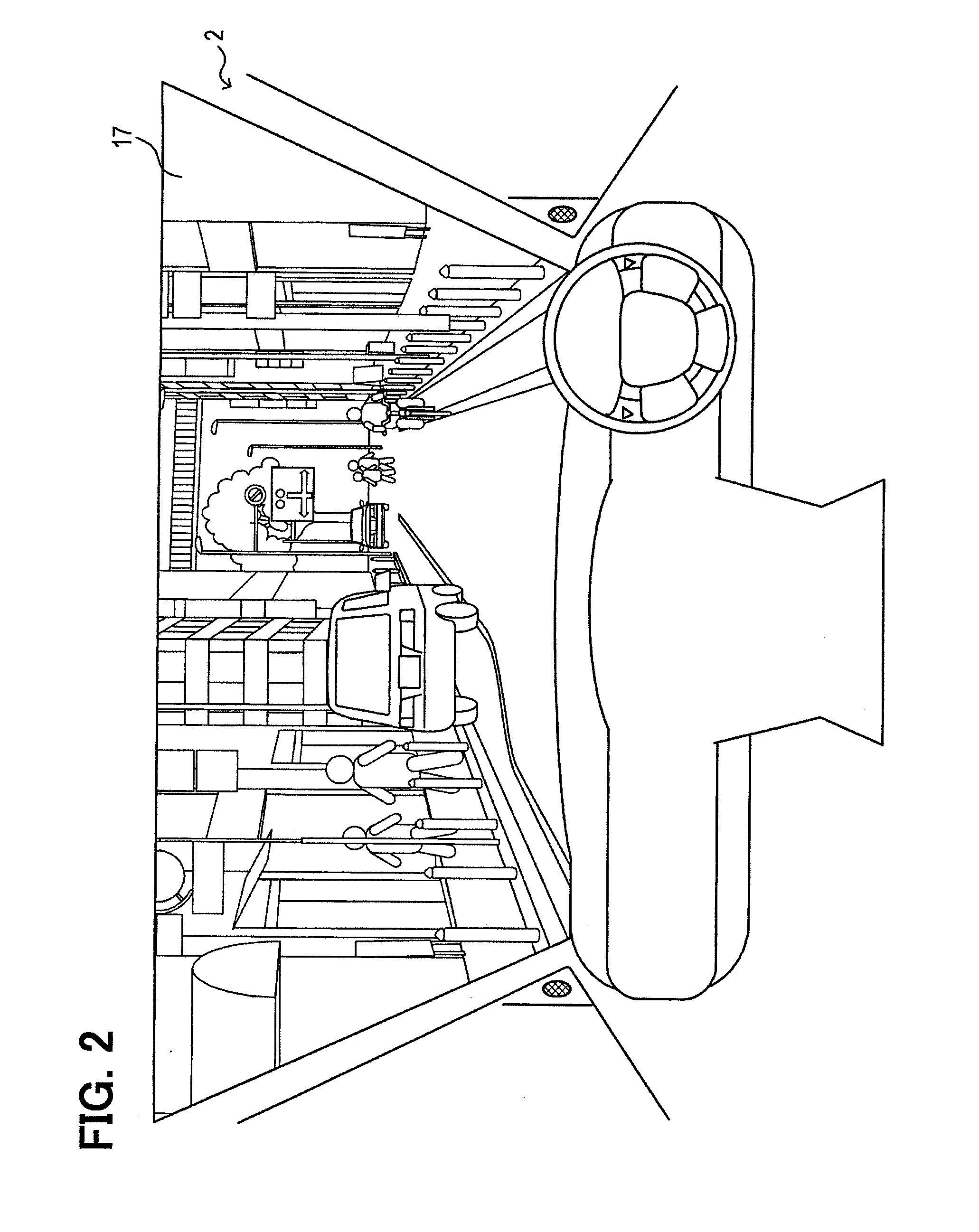
The in-vehicle display apparatus described in this patent text describes a technology that can prevent distraction for drivers by displaying important information in a virtual image in a wide, flat region in front of the vehicle, away from uneven or low-flatness areas such as traffic signals or road signs. The virtual image is displayed at a threshold size, which is designed to be large to prevent the virtual image from appearing too close to the uneven or low-flatness areas, which could cause the driver to not quickly recognize information necessary for safe driving. The technology also prevents the virtual image from being overlapped with another vehicle or person and ensures that the driver has a proper virtual image display that shows information useful for driving. This reduces the risk of driving accidents and provides a safer driving experience for drivers. The technology can also be applied to computer displays, making it easier to display important information safely and efficiently.

Problems solved by technology

Such a case may not permit the driver to promptly recognize the state of the traffic signal.
Such a case may decrease the visibility of the displayed picture or cause the information necessary for driving to be difficult for understanding.
Therefore, the in-vehicle display apparatus can reduce a possibility that causes a driver not to promptly recognize the state of a traffic signal or a possibility that decreases the visibility of the displayed picture.

Method used


Image

  • In-vehicle display apparatus and program product
  • In-vehicle display apparatus and program product
  • In-vehicle display apparatus and program product

Examples


Embodiment Construction

[0037]Hereinafter, description will be given to an in-vehicle display apparatus 1 according to an embodiment of the present disclosure with reference to drawings.

[0038]

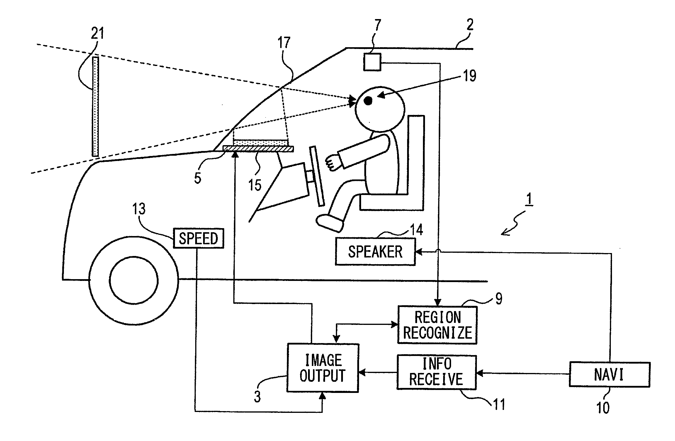
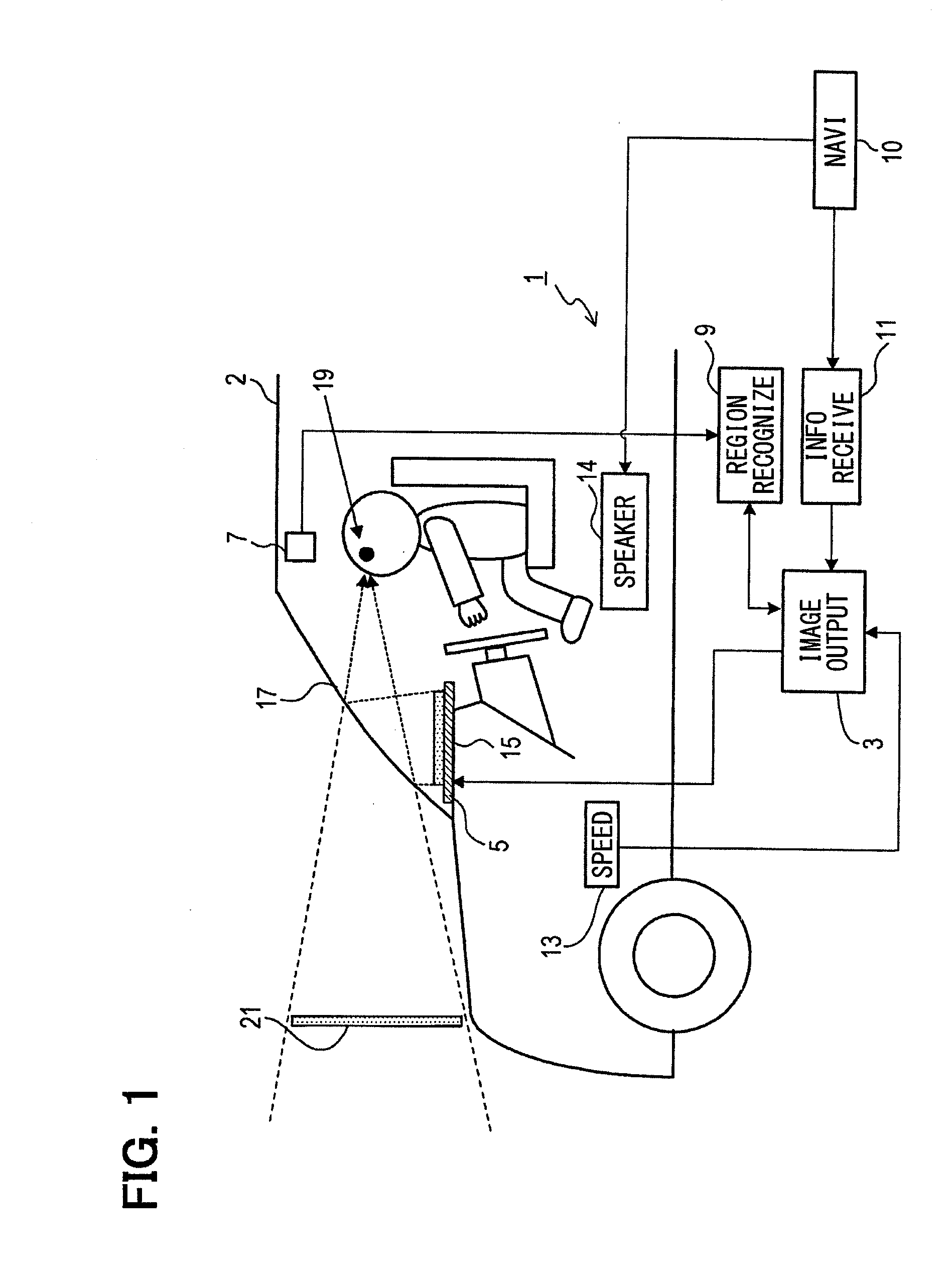
[0039]With reference to 9G. 1, the in-vehicle display apparatus 1 mounted in a vehicle 2 (i.e., a host vehicle) of a user includes an image output circuit (image control device or means) 3, a liquid crystal panel (virtual image display device or means) 5, a camera 7, a region recognition circuit (region recognition device or means) 9, a navigation system 10, an information reception circuit (information acquisition device or means) 11, a speed sensor 13, and a speaker 14.

[0040]The image output circuit 3 outputs picture data to a liquid crystal panel 5. The liquid crystal panel 5 is arranged on an instrumental panel 15, and displays a picture (i.e., an image) based on the picture data from the image output circuit 3; the liquid crystal panel 5 outputs light based on the displayed picture. The light outputted by the liq...


PUM


Abstract

An in-vehicle display apparatus in a vehicle includes a region recognition circuit and an image output circuit. The region recognition circuit recognizes a target plane region in scenery ahead of the vehicle; the target plane region corresponds to a continuous region having (i) a flatness equal to or greater than a predetermined threshold value and (ii) an area size equal to or greater than a predetermined threshold value. The image output circuit displays a driving information picture as a virtual image using a liquid crystal panel such that a driver of the vehicle views the virtual image in the target plane region within a displayable region through a windshield of the vehicle.

Description

CROSS REFERENCE TO RELATED APPLICATION[0001]The present application is based on Japanese Patent Application No. 2013-125596 filed on Jun. 14, 2013, the disclosure of which is incorporated herein by reference.TECHNICAL FIELD[0002]The present disclosure relates to an in-vehicle display apparatus and a related program product, which achieve a HUD (Head-Up Display) to perform a virtual image display of a picture indicating information useful for a driver.BACKGROUND ART[0003]Patent Literature 1: JP 2012-063524 A[0004]Patent Literature 2: JP-2008-501956 A (WO 2005421707 A2)[0005]Patent Literature 1 describes a head-up display (HUD), which projects light on a windshield or combiner in a vehicle and displays a variety of pictures to permit a driver to view them through a windshield. Further, Patent Literature 2 uses a HUD, which displays a guidance picture at a position corresponding to a road ahead of the vehicle as a virtual image that indicates the heading direction (route guide informat...

Claims


Application Information

Patent Timeline
IPC IPC(8): G06T11/60G06K9/00
CPCG06K9/00832G06T11/60B60K35/00G02B27/01G02B2027/0138G02B2027/014G06V20/59B60K35/28B60K2360/168B60K2360/169B60K35/23B60K2360/179B60K2360/177B60K35/29B60K2360/191B60K2360/178
Inventor IGUCHI, SEI
Owner DENSO CORP
Learn More