Lacrimal duct tube

a technology of lacrimal duct and duct tube, which is applied in the field of lacrimal duct tubes, can solve the problems of false passage, poor therapeutic effect, and tip end being prone to slide over the end surface of the reinforcement body,

Inactive Publication Date: 2014-12-11
KANEKA CORP
View PDF1 Cites 7 Cited by
  • Summary
  • Abstract
  • Description
  • Claims
  • Application Information

AI Technical Summary

Benefits of technology

[0016]According to the lacrimal duct tube according to the present invention, when the lacrimal duct tube is inserted into a lacrimal duct using an insertion aid, the tip end portion of the insertion aid is guided to and stopped at the stopper part with a cylindrical structure in the lacrimal duct tube, and thus the insertion aid does not greatly slip sideways when abutting against the stopper part, and it is possible to effectively reduce the possibility that the insertion aid protrudes from the leading end of the lacrimal duct tube or breaks through the side surface of the tube.

Problems solved by technology

However, the tube as shown in Patent Document 1 has a tip end of a blind-end structure, which causes a problem that a lacrimal fluid, a drug solution for verification of water passage at an examination, or the like stays in the lacrimal duct tube and is not discharged to the outside.
The bougies are blindly operated and thus may break through the tube or cut a hole at a site other than in the normal lacrimal tube (creating a false passage), which results in poor therapeutic outcomes.
However, the end surface of the reinforcement body is flat, and thus when the tip end of the bougie or the like abuts against the end surface of the reinforcement body, the tip end is prone to slide over the end surface of the reinforcement body.
Accordingly, there is a fear that, if an excessive force acts on the lacrimal duct tube when the lacrimal duct tube is bent or guided into a obstructed lacrimal duct, the tip end of the bougie or the like slips sideways on the end surface of the reinforcement body, and the tip end of the bougie or the like breaks through the side surface of the tube, which results in damage to the lacrimal duct or creation of a false passage.

Method used


Image

  • Lacrimal duct tube
  • Lacrimal duct tube
  • Lacrimal duct tube

Examples


Embodiment Construction

[0020]The present invention will be described below in more detail.

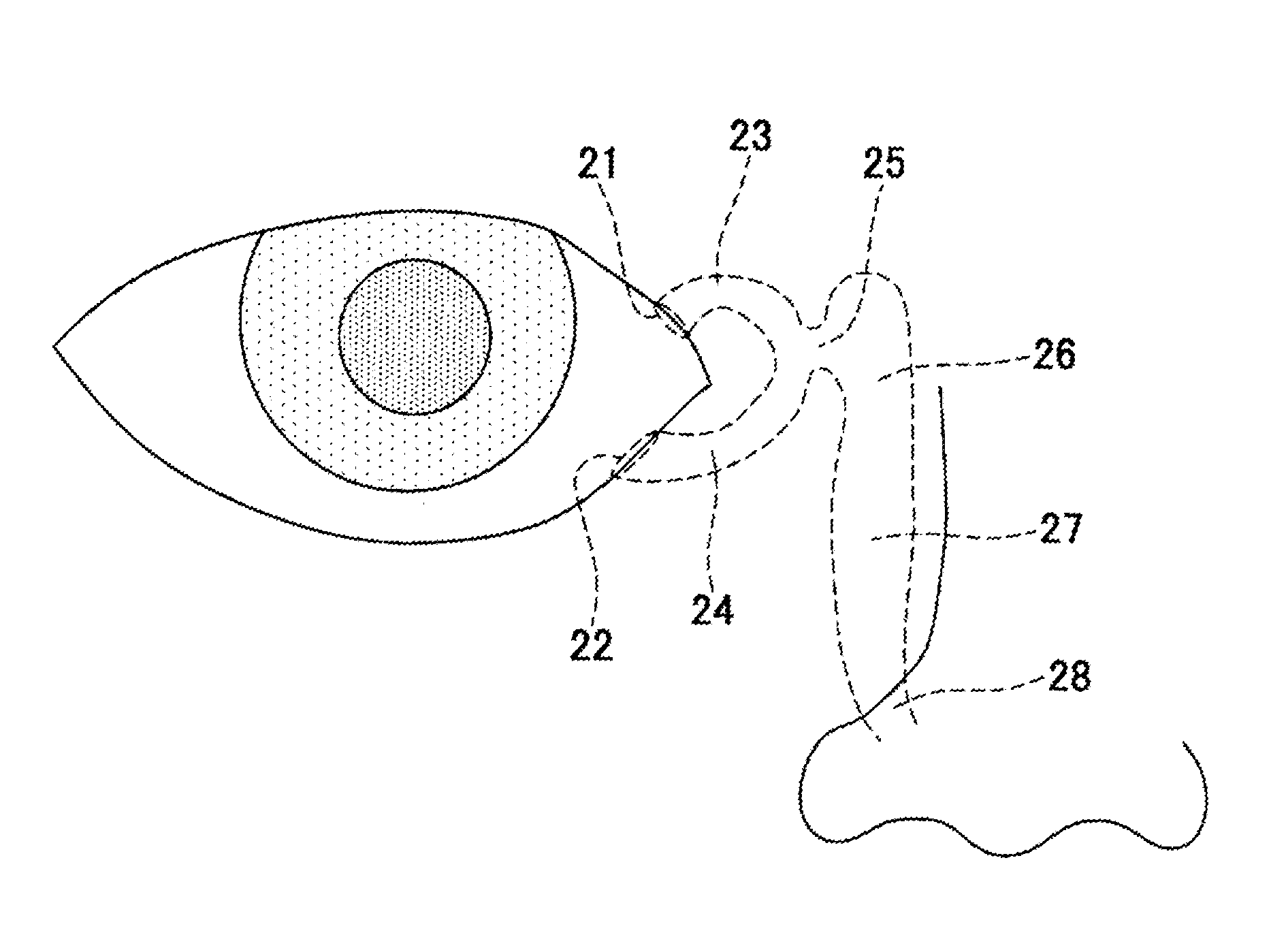
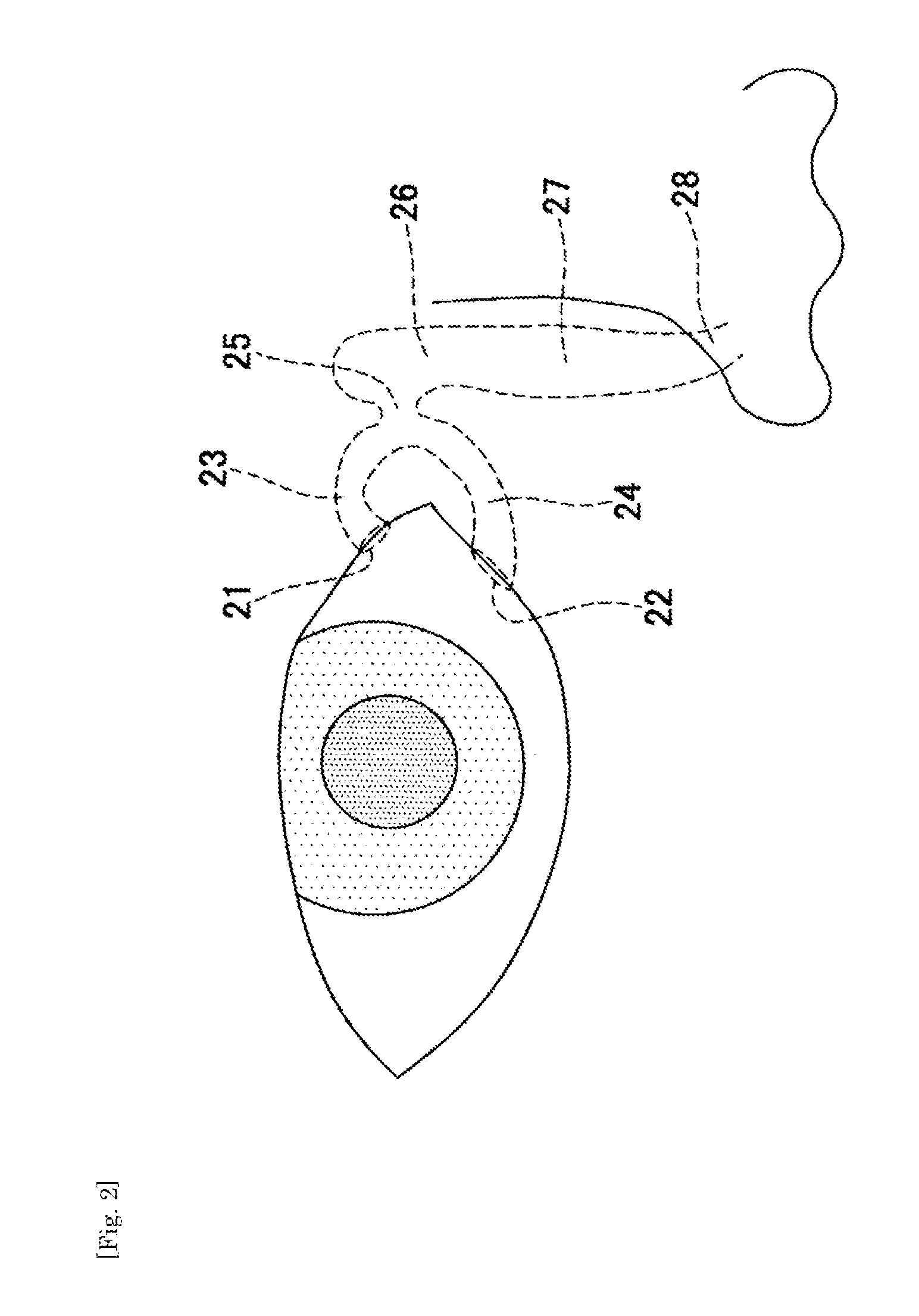
[0021]Lacrimal duct referred to in the present invention is a duct (ocular adnexa) composed of upper / lower lacrimal punctum (21 / 22), upper / lower lacrimal canaliculus (23 / 24), a common canaliculus (25), a lacrimal sac (26), a nasolacrimal duct (27), a nasal cavity (not shown), and Hasner's valve (not shown), as shown in FIG. 2, and configured to guide a lacrimal liquid produced by a lacrimal gland (not shown) from an eye surface to an inferior nasal meatus (28). FIG. 2 shows schematically an anatomical structure of a lacrimal duct. In addition, a duct extending from the upper lacrimal punctum (21) through the upper lacrimal canaliculus (23), and the common canaliculus (25) to the inferior nasal meatus (28) is referred to as an upper lacrimal duct, and a duct extending from the lower lacrimal punctum (22) through the lower lacrimal canaliculus (24), and the common canaliculus (25) to the inferior nasal meatus (28) is r...


PUM


Abstract

A lacrimal duct tube (31) includes an integrated tube that is placed in a lacrimal duct and capable of insertion of an insertion aid (36) in a detachable manner. The tube (31) has a terminal end opening (33) at a terminal end. In the vicinity of the terminal end opening (33), a stopper part (32a, 32b, 32c, and 32d) for stopping the insertion aid (36) is inserted in the tube (31). The stopper part (32a, 32b, 32c, and 32d) is opened at both ends in an axial direction of the tube and has a cylindrical structure including an inner wall surface (37a, 37b, 37c, and 37d) to guide and stop the insertion aid (36).

Description

TECHNICAL FIELD[0001]The present invention relates to a lacrimal duct tube for use in treatment of lacrimal duct obstruction.BACKGROUND ART[0002]Treatment methods for lacrimal duct obstruction resulting in epiphora include: (i) probing by a lacrimal duct bougie, (ii) placement of a lacrimal duct intubation instrument; (iii) dacryocystorhinostomy (DCR); (iv) lacrimal canaliculoplasty; (v) nasolacrimal duct plasty; (vi) lacrimal caruncle moving surgery, and the like.[0003]The probing by a lacrimal duct bougie in (i) is intended to insert a narrow tube called bougie into a lacrimal duct to open an obstructed site and reconstruct a flow path for a lacrimal fluid. This method is conducted as a first treatment in many cases due to its ease of execution and minimal invasiveness. The treatments (iii) dacryocystorhinostomy (DCR), (iv) lacrimal canaliculoplasty, (v) nasolacrimal duct plasty, (vi) lacrimal caruncle moving surgery are highly effective but relatively invasive because of the need...

Claims


Application Information

Patent Timeline
Patent Type & Authority Applications(United States)
IPC IPC(8): A61F9/007
CPCA61F9/00772
Inventor MATSUMOTO, MARIKOMIYAUCHI, HIDEKAZU
Owner KANEKA CORP
Why Eureka
Try Eureka