Systems and method for controlling warnings at vehicle crossings

a vehicle crossing and warning technology, applied in railway traffic control, traffic gates, railway signalling and safety, etc., can solve the problems of long warning time, inability to accurately predict inability to accurately detect the speed of vehicles,

Active Publication Date: 2014-12-11
GENERAL ELECTRIC CO
View PDF8 Cites 24 Cited by
  • Summary
  • Abstract
  • Description
  • Claims
  • Application Information

AI Technical Summary

Benefits of technology

The patent involves a system that receives information about when a vehicle system will move and uses it to notify other vehicles of the arrival or departure of the vehicle system at a crossing between two routes. The system then controls warning devices to either notify or prevent other vehicles from traveling through the crossing. The technical effect is the increased safety and efficiency of the system by providing advance notification and control to other vehicles.

Problems solved by technology

In some systems, for example rail systems that use catenaries or third rails to provide energy to rail vehicles, electrical interference may be too high for predictor systems to function accurately.
Long warning times can be undesirable because of the unnecessary delay caused to operators of other vehicles trying to move through the crossing.
Traditional predictor circuits are limited by practical considerations to a range extending a given distance from a crossing.
In such systems, crossings will frequently activate earlier than desired, resulting in overly long waiting periods, and resulting in inconsistent wait times for operators of vehicles waiting at the crossing.
Such systems also fail to address issues resulting from relatively slower speeds of the vehicle that is approaching the crossing.
Because only a single message is communicated from the onboard system to the wayside unit, this single message may not be received and / or may be degraded or interfered with due to various problems with communication and / or external interferences with communication.
Because of this additional, built-in buffer time period, the warning system may activate too soon and other vehicles at the crossing may be warning of the approaching vehicle too soon.
As described above, impatient operators of these other vehicles may attempt to circumvent such a warning system by attempting to drive through the crossing ahead of the approaching vehicle.

Method used


Image

  • Systems and method for controlling warnings at vehicle crossings
  • Systems and method for controlling warnings at vehicle crossings
  • Systems and method for controlling warnings at vehicle crossings

Examples


Embodiment Construction

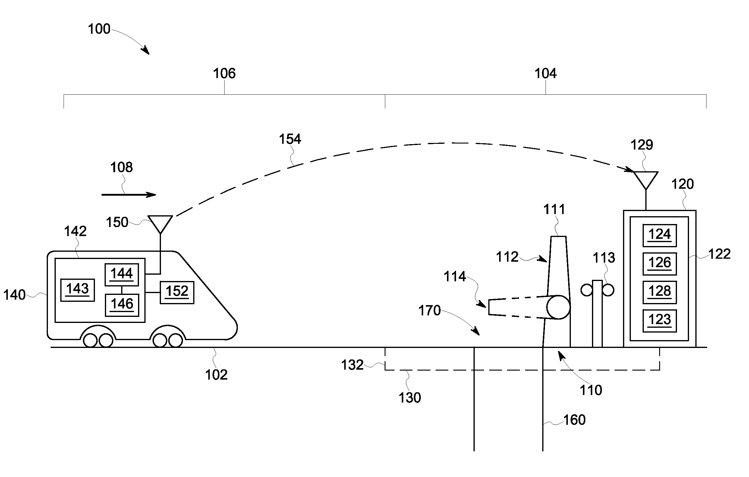
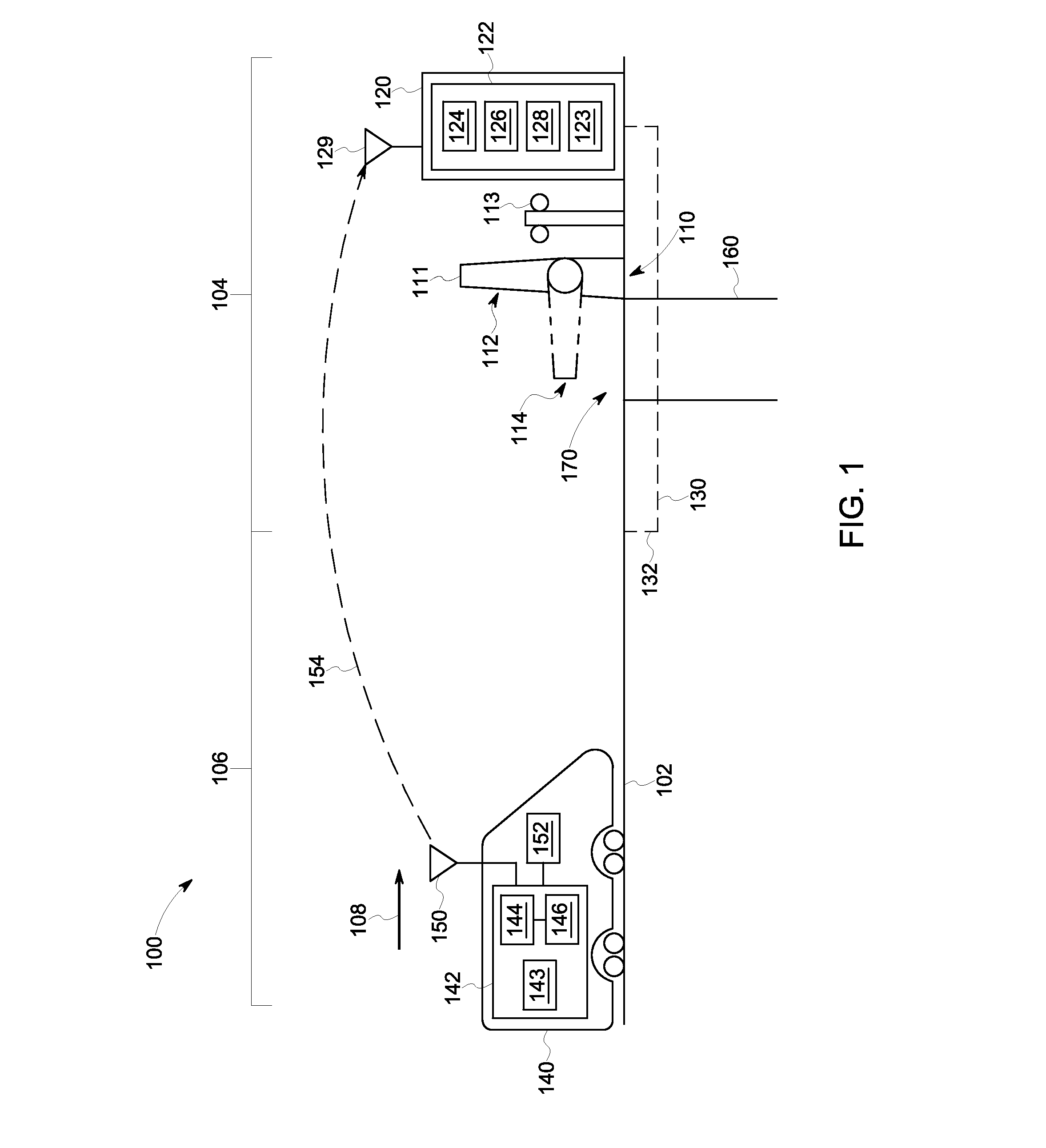
[0021]One or more embodiments of the inventive subject matter described herein provide systems and methods for improved operation of crossings for transportation systems, such as crossings associated with an intersection between a rail system and a road or highway system. In various embodiments, an onboard system is provided that is configured to control movement of a rail vehicle and to communicate with a crossing module or system, such as wayside equipment controlling the crossing. The control systems for the rail vehicle, for example, may be configured to be compatible with Positive Train Control (PTC) systems utilized in the United States. In various embodiments, bidirectional communications between onboard equipment and wayside equipment may be used to activate and deactivate crossing warning (or closing) systems when necessary to provide a substantially consistent amount of warning time. For example, the crossing warning systems may be activated no longer than a designated amo...


PUM


Abstract

A method includes receiving an absolute time associated with movement of a vehicle system, modifying the absolute time into a relative time, and controlling one or more warning devices using the relative time. A system includes a crossing module configured to receive an absolute time associated with movement of a vehicle system. The crossing module is configured to modify the absolute time into a relative time and to control one or more warning devices using the relative time.

Description

CROSS-REFERENCE TO RELATED APPLICATIONS[0001]This application claims priority to U.S. Provisional Patent Application No. 61 / 835,830, which was filed on 17 Jun. 2013, and is titled “Systems And Methods For Controlling Warnings At Vehicle Crossings” (referred to herein as the “'830 application”). This application also is a continuation-in-part of U.S. patent application Ser. No. 13 / 910,412, which was filed on 5 Jun. 2013, and is titled “Systems And Methods For Providing Constant Warning Time At Crossings” (referred to herein as the “'412 application”). The entire disclosures of the '830 application and the '412 application are incorporated by reference.FIELD[0002]Embodiments of the subject matter described herein relate to vehicle location systems and methods, and more particularly, to systems and methods for providing warning times at crossings.BACKGROUND[0003]A vehicle transportation system may include routes over which vehicles travel. These routes may cross routes of other transpo...

Claims


Application Information

Patent Timeline
IPC IPC(8): B61L29/04
CPCB61L29/04B61L29/32B61L29/22
Inventor STEFFEN, MICHAELHERLOCKER, JESSEFRIES, JEFFREY MICHAEL
Owner GENERAL ELECTRIC CO
Why Eureka
Try Eureka