Hair dryer

Active Publication Date: 2014-11-27
JEMELLA
View PDF14 Cites 4 Cited by
  • Summary
  • Abstract
  • Description
  • Claims
  • Application Information

AI Technical Summary

Benefits of technology

The patent describes a hair dryer with a filter plate that has holes aligned along a spiral pattern. The holes are designed to reduce noise caused by the blades of the impeller. The filter plate can be easily replaced with different filters, allowing users to customize the hair dryer with different filters. The technical effects of this design include reduced noise, improved efficiency, and easy interchange of filters.

Problems solved by technology

However such filters can cause problems because over time dust and other debris builds up in the filter, reducing the air pressure and with more severe clogging causing overheating of the element and cyclical cutting-out the hair dryer resulting in a hot / cold air flow.

Method used


Image

  • Hair dryer
  • Hair dryer
  • Hair dryer

Examples


Embodiment Construction

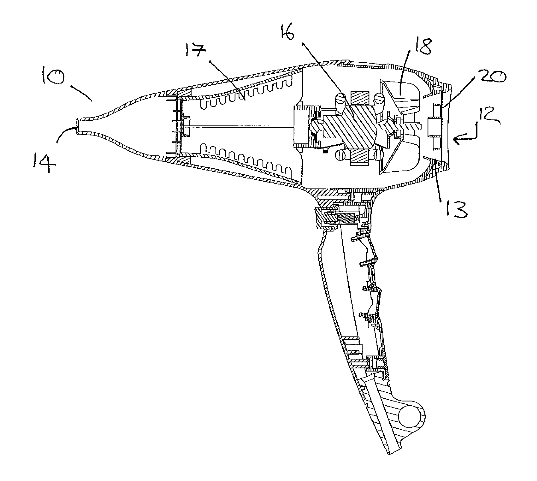
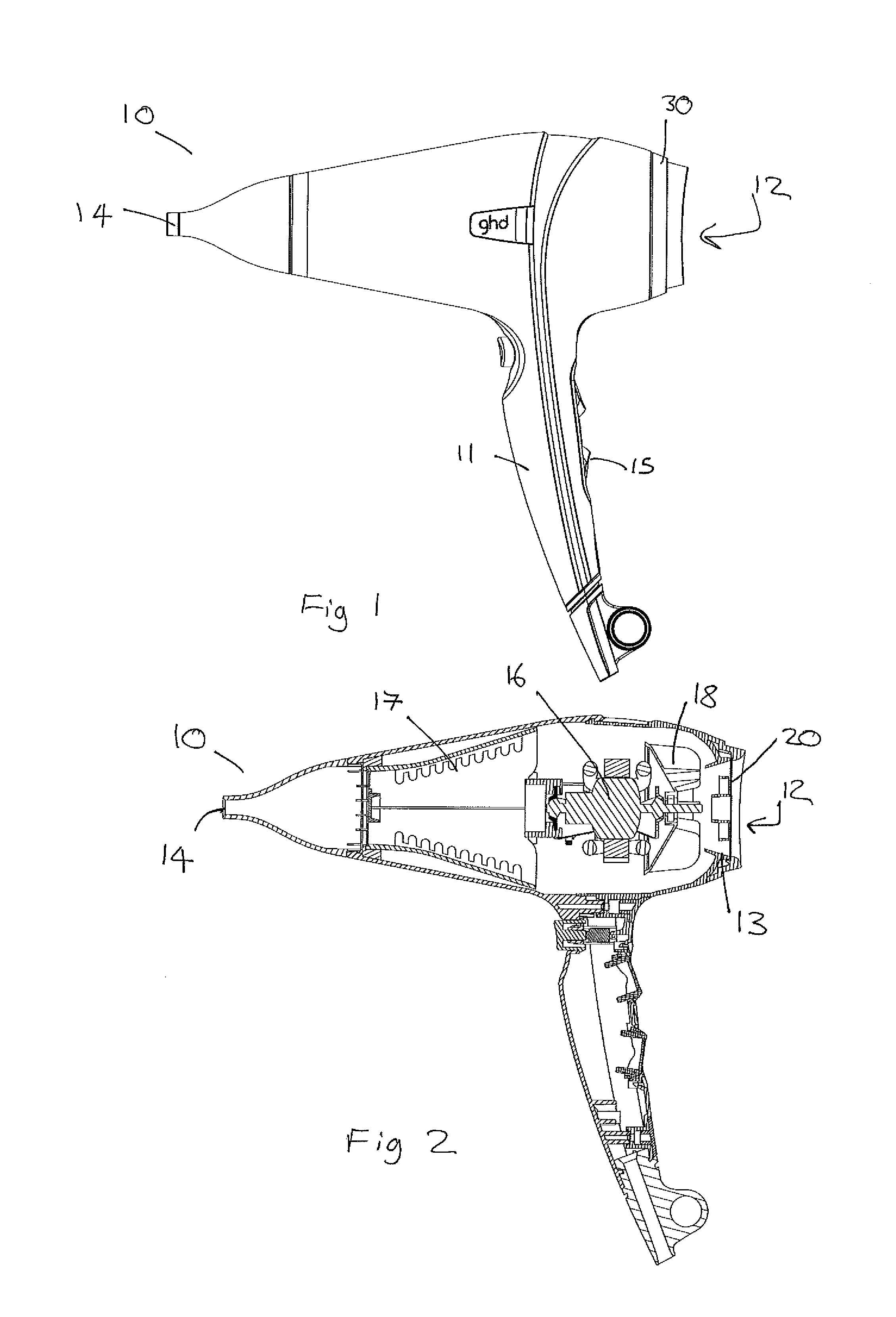
[0031]FIG. 1 shows a side view of a hair dryer 10 and FIG. 2 shows a cross sectional view of hair dryer 10 according to an embodiment of the invention. The hair dyer has an air inlet 12, an air outlet 14, a motor 16 located between the inlet 12 and outlet 14. The motor 16 powers an impeller 18 which draws in air axially from the inlet 12 and expels air radially from the impeller towards outlet 14. A heating element 17 is located between the motor and outlet to heat the air before it is expelled through the outlet. Attached to the handle 11 are controls 15 for turning the hair dryer on and off, controlling the rotational speed of the motor (and thereby controlling the flow rate of expelled air) and temperature of the expelled air.

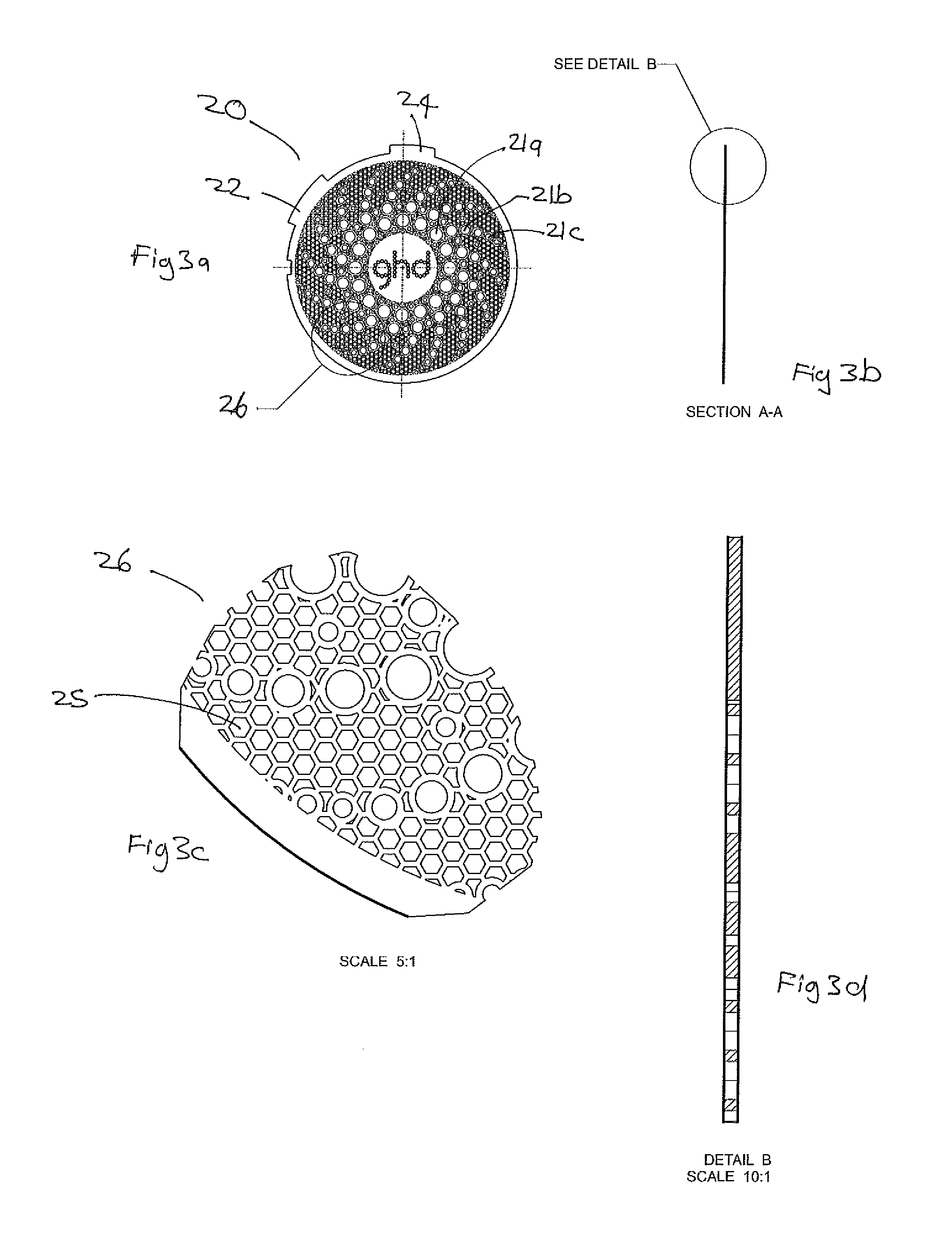
[0032]Coupled to the rear of the hair dryer, about the air inlet 12, a metal filter plate 20 is mounted in a filter mount 30. The metal filter plate 20 attaches to the filter mount 30, the filter mount then attaches to the rear of the hair dryer so that the ...


PUM


Abstract

A hair dryer (10) has a hand-held housing comprising an air inlet (12), an air outlet (14), a motor (1) between said air inlet (12) and said air outlet (14) to draw air in from said air inlet (12) and drive air out from said air outlet (14). A heating element (17) is located in said air flow between said air inlet (12) and said air outlet (14). The hair dryer (10) further comprises a filter on said air inlet (12). The filter comprises a metal filter plate (20) bearing a plurality of holes, wherein at least some of said holes have a maximum lateral dimension of less than 1.5 mm and wherein vertical walls of said holes through a thickness of said filter plate are substantially straight or at least partially concave.

Description

FIELD OF THE INVENTION[0001]The invention relates to improved air filters for hair dryers, and to methods of manufacture of such filters.BACKGROUND TO THE INVENTION[0002]A typical hand-held hair dryer comprises a hand-held housing with an air inlet, an air outlet, and a motor in between to draw air in from the air inlet and drive air out from the air outlet. A heating element is located in the air flow between the air inlet and the air outlet, typically after the motor in the air flow.[0003]In some preferred implementations of a hair dryer the motor is coupled to a mix flow impeller, which draws air in axially and generates a high air pressure by thrusting the air outwards, where it is confined by the housing and forced through the hair dryer air outlet. The high pressure achieved by such a technique is useful in forcing apart the strands of hair.[0004]Typically a hair dryer is provided with a filter on the air inlet which, among other things, stops hair from being accidentally draw...

Claims


Application Information

Patent Timeline
IPC IPC(8): A45D20/08F26B21/00
CPCF26B21/003A45D20/08A45D20/12A45D20/10A45D20/122
Inventor SAYERS, STEPHEN ANTHONYWEATHERLY, ROBERT ALEXANDERBRADY, DANIEL
Owner JEMELLA
Why Eureka
Try Eureka