
Mechanical Friction Enhancement for Threaded Connection Incorporating Opposing Barb

a technology of opposing barbs and mechanical friction enhancement, which is applied in the direction of packaging foodstuffs, packaged goods types, pharmaceutical containers, etc., can solve the problems of serious contamination risk for patients and/or other people in the vicinity of the disconnected medical connector, and the components of the connector may be accidentally or inadvertently unscrewed,

Active Publication Date: 2014-11-20
BECTON DICKINSON & CO
View PDF2 Cites 6 Cited by
  • Summary
  • Abstract
  • Description
  • Claims
  • Application Information

AI Technical Summary

Benefits of technology

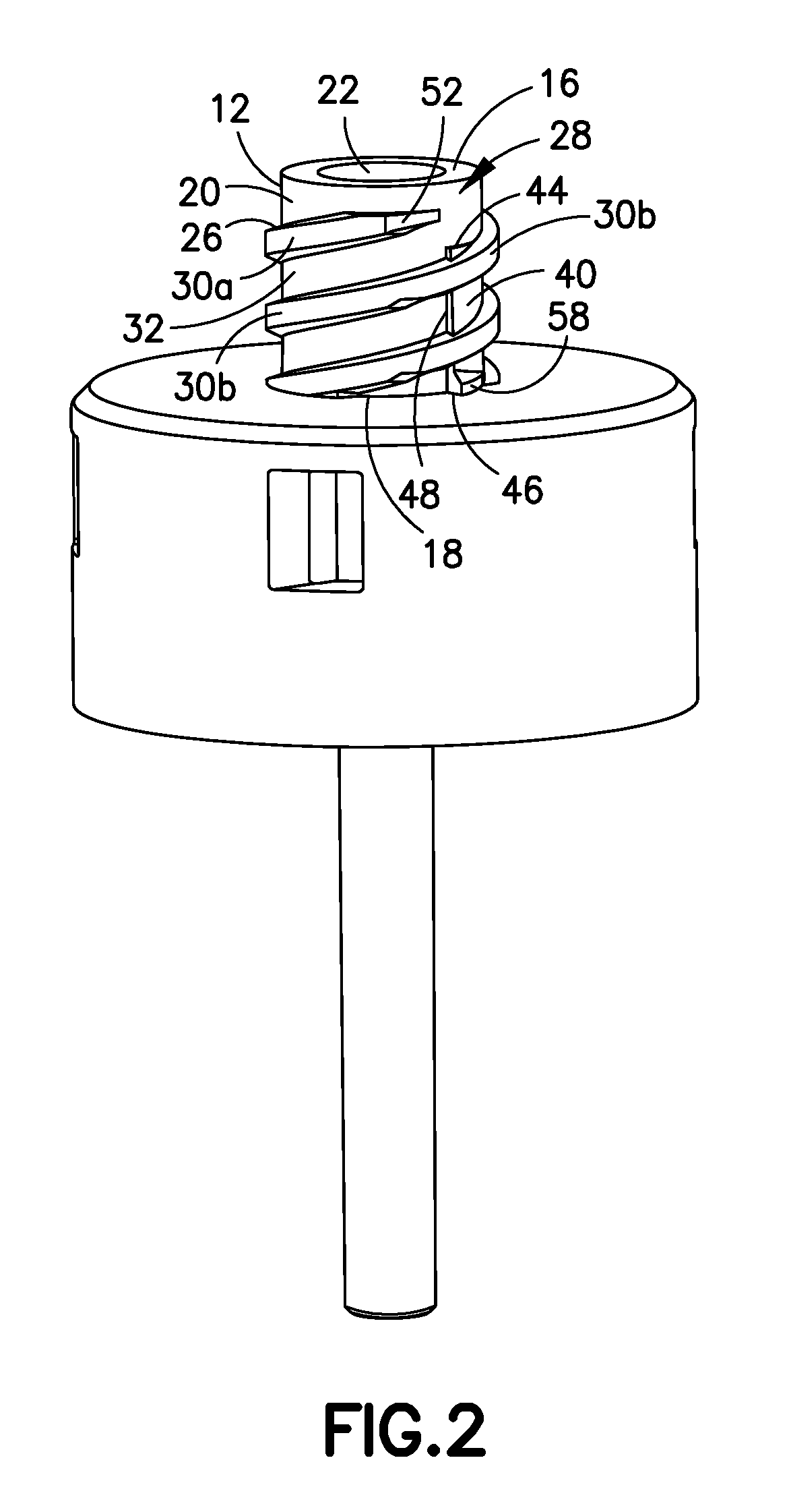
The patent describes a medical connector with a helical thread and a protrusion that increase friction to prevent leakage when connected to another connector. The protrusion has a tapered shape, with a wider base and a narrower top, and a maximum radial height that increases towards the distal end of the connector. The connector may also have a stop to prevent further advancement of the mating connector. The technical effect of this design is to improve the reliability and security of the medical connection.

Problems solved by technology

However, once the male luer-lock element has been screwed into the female luer-lock element of the connector, there is a risk that the connector components may be accidentally or inadvertently unscrewed, which could lead to the disconnection of the fluid passage.
This may entail a serious contamination risk for a patient and / or any other person in the vicinity of the disconnected medical connector.
In addition, when the friction between the female luer-lock and the male luer-lock is low, there is a tendency for users to over-torque the connection because there is no discernable indication that the connection has been fully tightened.
This can lead to breakage of the connectors and / or the containers being joined.

Method used


Image

  • Mechanical Friction Enhancement for Threaded Connection Incorporating Opposing Barb
  • Mechanical Friction Enhancement for Threaded Connection Incorporating Opposing Barb
  • Mechanical Friction Enhancement for Threaded Connection Incorporating Opposing Barb

Examples


Embodiment Construction

[0022]For purposes of the description hereinafter, the terms such as “end”, “upper”, “lower”, “right”, “left”, “vertical”, “horizontal”, “top”, “bottom”, “lateral”, “longitudinal”, and derivatives thereof shall relate to the invention as it is oriented in the drawing figures. However, it is to be understood that the invention may assume various alternative variations and step sequences, except where expressly specified to the contrary. It is also to be understood that the specific devices and processes illustrated in the attached drawings, and described in the following specification, are simply exemplary embodiments of the invention. Hence, specific dimensions and other physical characteristics related to the embodiments disclosed herein are not to be considered as limiting. Further, it is to be understood that the invention may assume various alternative variations and step sequences, except where expressly specified to the contrary.

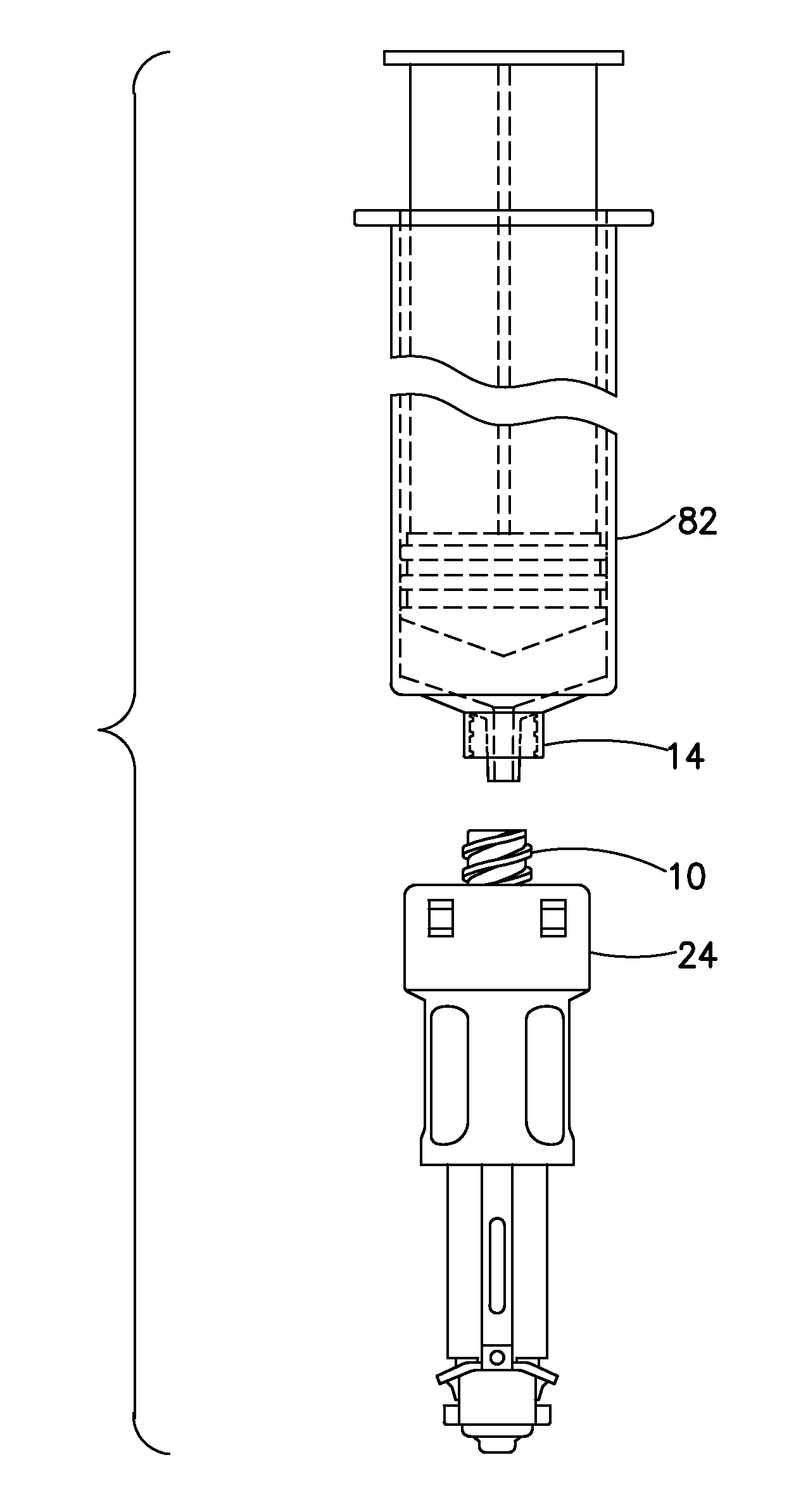
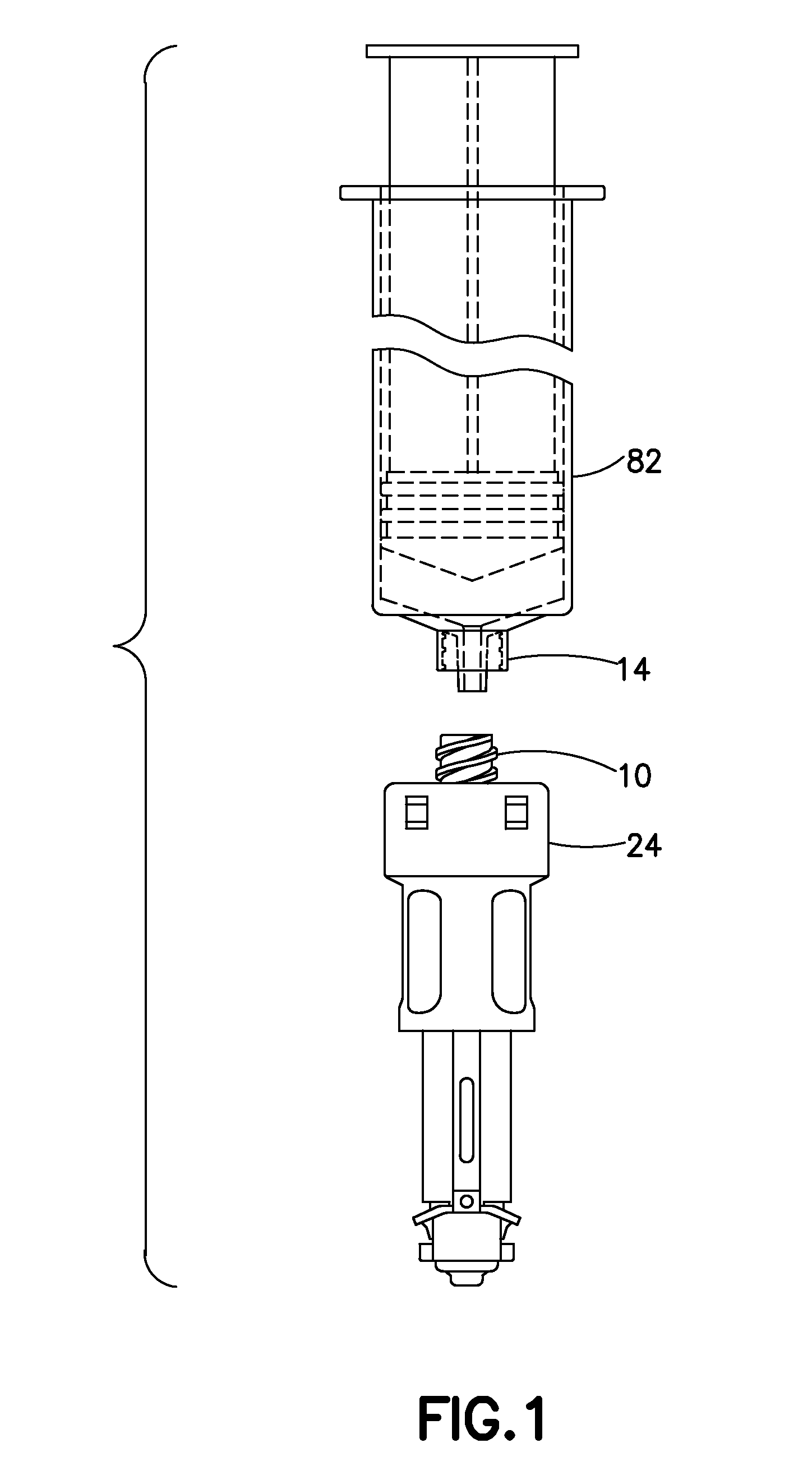
[0023]Referring to FIG. 1, a conventional syring...


PUM

PropertyMeasurementUnit
angleaaaaaaaaaa
radial heightaaaaaaaaaa
circumferential widthaaaaaaaaaa

Abstract

A medical connector includes a body having a distal end, a proximal end, and a sidewall extending between the distal end and the proximal end. The medical connector further includes a helical thread extending radially outward from a surface of the sidewall and at least one protrusion extending radially outward from a surface of the sidewall. The at least one protrusion has a first side and a second side. A radial height of the at least one protrusion from the surface of the sidewall tapers circumferentially from the first side of the at least one protrusion to the second side of the at least one protrusion.

Description

CROSS-REFERENCE TO RELATED APPLICATION[0001]This application claims priority to U.S. Provisional Application Ser. No. 61 / 824,163, filed May 16, 2013, which is hereby incorporated by reference in its entirety.BACKGROUND OF THE INVENTION[0002]1. Field of the Invention[0003]The present invention relates to a connector for enabling fluid transfer between a first fluid container and a second fluid container. More specifically, the invention is directed to a connector having structure to increase friction between threaded connection portions.[0004]2. Description of Related Art[0005]Many medical connectors comprise a first component having a female luer-lock element that is arranged to be rigidly joined to a corresponding male luer-lock element of a second connector component that is attached to a medical line or other medical connection, for example. The male luer-lock element can, thus, be freely screwed into and unscrewed from the female luer-lock element. However, once the male luer-lo...

Claims


Application Information

Patent Timeline
Patent Type & Authority Applications(United States)
IPC IPC(8): A61J1/20
CPCA61J1/2096A61M39/1011A61M2039/1033A61M2039/1044Y10T29/49948
Inventor CEDERSCHIOLD, ALEXANDERGILBERT, ANGELACARNEY, CHRISTOPHER
Owner BECTON DICKINSON & CO
Learn More