Utility vehicle with a continuously variable transmission having a system for selectively establishing a fixed maximum transmission ratio

a continuously variable transmission and transmission ratio technology, applied in mechanical equipment, transportation and packaging, gearing, etc., can solve the problems of inability the rotational speed of the spray pump will correspondingly slow down, and the transmission ratio does not permit one to maintain a constant application ra

Active Publication Date: 2014-11-13
TORO CO THE
View PDF2 Cites 7 Cited by
  • Summary
  • Abstract
  • Description
  • Claims
  • Application Information

AI Technical Summary

Benefits of technology

This patent is about a type of transmission used in vehicles and a vehicle that uses it. The transmission has a pulley with two movable sheaves and a flexible belt that can change the ratio of transmission between a minimum and maximum. A selectively deployable stop is on the pulley, which can be moved to limit the movement of the sheaves and thus the range of ratios. This stop can be adjusted to control the maximum speed of the vehicle. The vehicle also has a belt type continuously variable transmission in its drive train, which allows for smooth shifting between the minimum and maximum ratios. The vehicle can be used to apply substances to the ground or turf surface at a desired rate proportional to its speed. This ensures a constant application rate even when the vehicle goes up or down hills.

Problems solved by technology

For example, if going up a hill, the vehicle may slow down through engine lug, but the rotational speed of the spray pump will correspondingly slow down as it is also being driven by the engine.
These constant changes in transmission ratio do not permit one to maintain a constant application rate as the rate of flow through the spray nozzles remains constant despite these variations in the vehicle ground speed.
However, this is a relatively expensive and complex control system that is not economically suited for the fairly simple spray operations of the type that would be conducted by utility vehicles.

Method used


Image

  • Utility vehicle with a continuously variable transmission having a system for selectively establishing a fixed maximum transmission ratio
  • Utility vehicle with a continuously variable transmission having a system for selectively establishing a fixed maximum transmission ratio
  • Utility vehicle with a continuously variable transmission having a system for selectively establishing a fixed maximum transmission ratio

Examples


Embodiment Construction

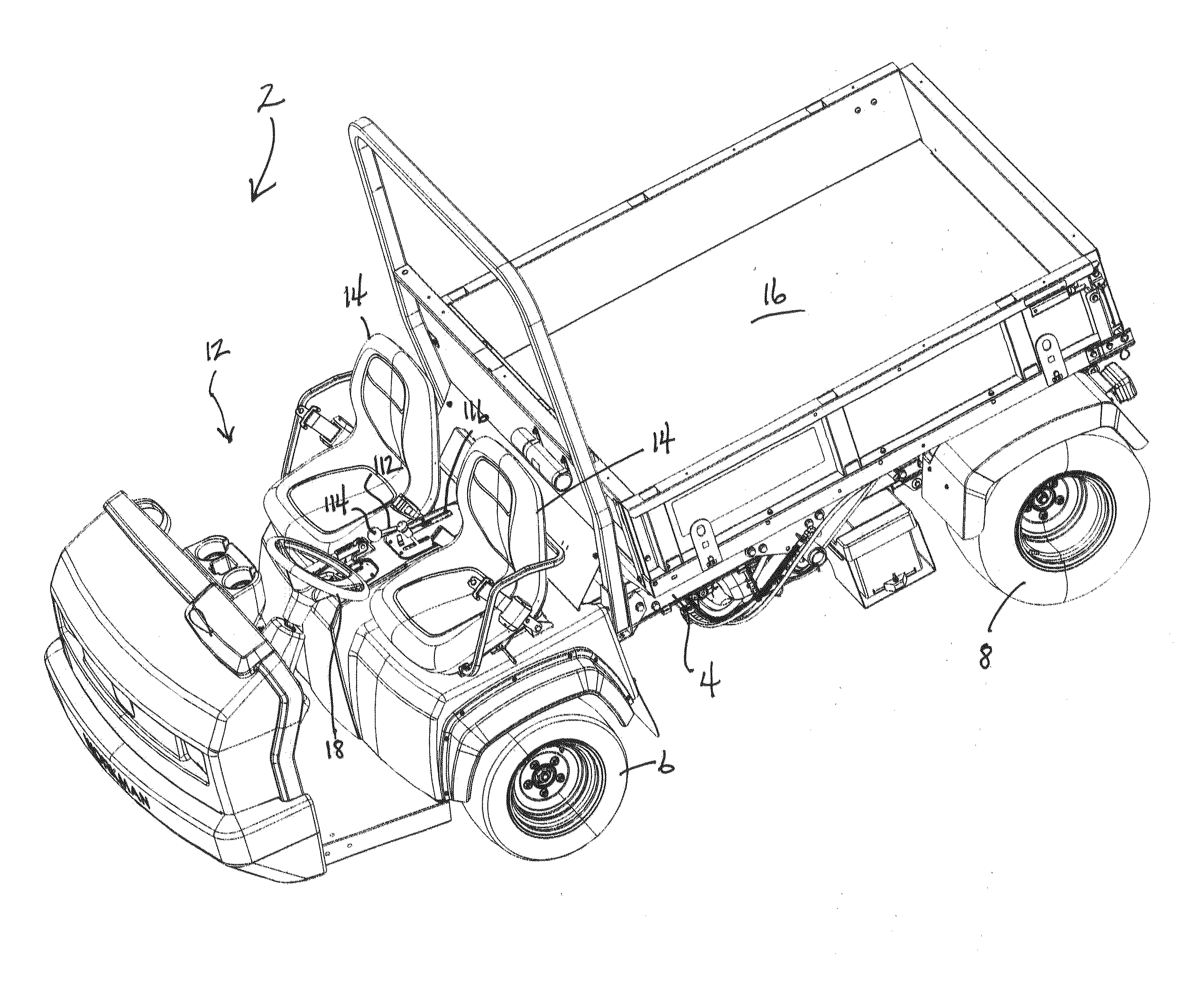
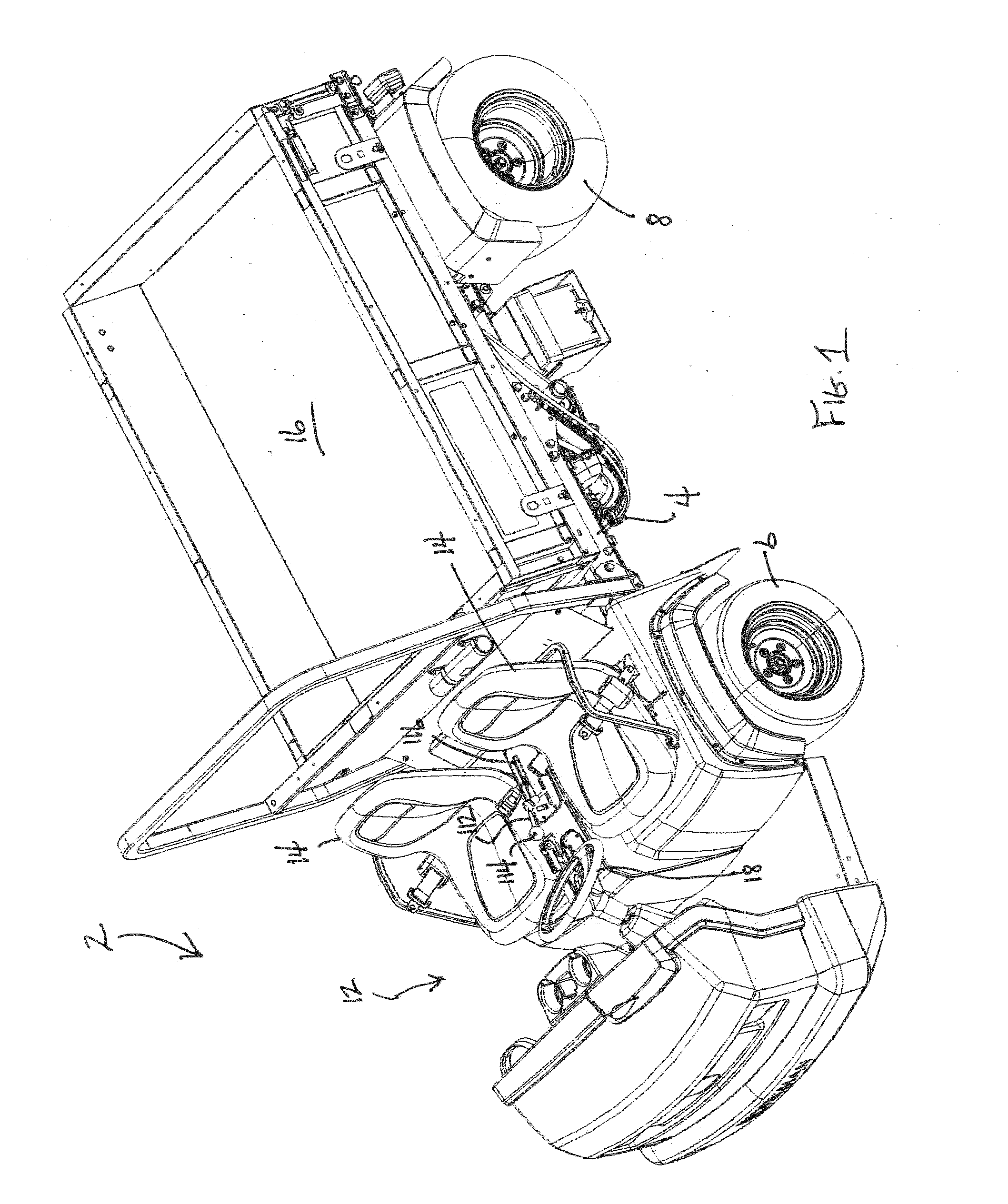
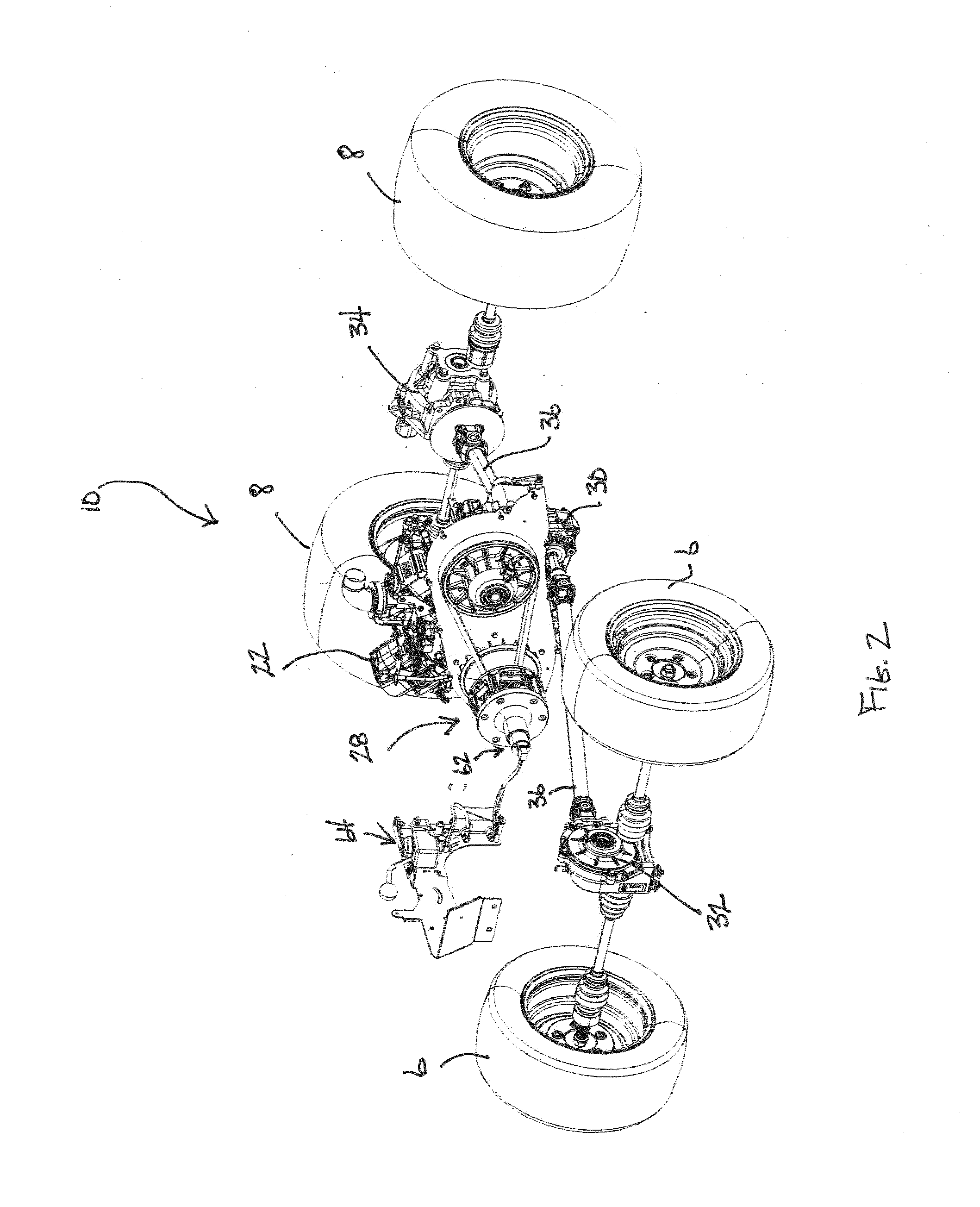
[0018]One embodiment of a utility vehicle which could advantageously use this invention is illustrated in FIG. 1 generally as 2. Vehicle 2 includes a frame 4 that is supported for rolling over the ground by a pair of front wheels 6 and a pair of rear wheels 8. Vehicle 2 also includes a drive train, illustrated generally as 10 in FIGS. 2 and 3, for powering front wheels 6 and rear wheels 8 in a four wheel drive (4WD) configuration to cause vehicle 2 to be self-propelled. Vehicle 2 shown in FIG. 1 is a utility vehicle from the Workman® line of utility vehicles manufactured and sold by The Toro Company, the assignee of this invention.

[0019]An open front compartment 12 is provided on frame 4 for carrying a driver and a passenger in side-by-side seats 14. A hydraulically actuated, pivotal dump box 16 is carried on frame 4 and extends from behind front compartment 12 to the rear end of vehicle 2. Front wheels 6 of vehicle 2 are steerable by the driver using a steering wheel 18 in advance ...


PUM


Abstract

A continuously variable transmission for a vehicle comprises a primary pulley, a secondary pulley, and a belt entrained around both pulleys in an opposite manner between the fixed and movable sheaves thereof. One pulley carries a selectively deployable stop that may be placed into position to mechanically limit the range of motion between the fixed and movable sheaves. This establishes an actual maximum transmission ratio that is larger than the nominal minimum transmission ratio but smaller than the nominal maximum transmission ratio achievable by the transmission during normal operation thereof. When such a transmission is used on a utility vehicle attached to a substance dispensing applicator operatively driven by the vehicle's engine, the application rate stays substantially constant despite changes in engine speed when the user keeps the transmission upshifted to the actual maximum transmission ratio set by the position of the deployed stop.

Description

TECHNICAL FIELD[0001]This invention relates to a utility vehicle used for outdoor work purposes such as ground or turf grooming operations, construction activities, farm or ranch tasks, and the like. More particularly, this invention relates to a utility vehicle that has a traction drive train which includes a continuously variable transmission.BACKGROUND OF THE INVENTION[0002]Utility vehicles are small, open vehicles designed for carrying a driver and a passenger in a side-by-side configuration at the front of the vehicle with a load carrying dump box being situated behind them. When used in the ground or turf grooming industry, the vehicle dump box might carry a pile of dirt or sand, or a plurality of rolls of sod, or many other things that are typically used for establishing, grooming or repairing ground or turf surfaces, such as the grass or sand traps found on a golf course. In addition to their basic load carrying and transportation functions, utility vehicles are often used a...

Claims


Application Information

Patent Timeline
IPC IPC(8): F16H9/12B60K17/08
CPCF16H9/125B60K17/08F16H2061/66213F16H63/065F16H9/18F16H55/563
Inventor LARSON, JAMIE R.FOHRENKAMM, JEREMY A.
Owner TORO CO THE
Why Eureka
Try Eureka