
Method for manufacturing a rope, a rope and an elevator

Inactive Publication Date: 2014-10-30
KONE CORP
View PDF4 Cites 5 Cited by
  • Summary
  • Abstract
  • Description
  • Claims
  • Application Information

AI Technical Summary

Benefits of technology

The invention provides an improved method for manufacturing a rope. The method involves guiding together and fixing pre-manufactured load bearing members and surface parts that are designed with optimal structure and manufacturing process for them. This allows for easy and accurate integration of the load bearing members and surface parts, regardless of their internal shapes. The fixed parts can also have discontinuous surface shapes and don't require complex internal structures. The fixing is carried out by heating and cooling the thermoplastic material used for the surface parts and load bearing members. This simplifies the fixing process and allows for the use of the parts without additional substances. Overall, the invention provides a simple and efficient way to manufacture ropes with precise structures.

Problems solved by technology

Adhesion between the parts is particularly important if the load-bearing part has a smooth surface and / or the load-bearing members are wide, because this means that mechanical interlocking between the parts is likely to be low.
Also, this kind of load-bearing members don't have a large surface area compared to cross-section area and the bond of the surface part and the load bearing member may become critical.
The risk is that the surface part breaks off the load bearing members.
A problem with this method has been that the components are difficult to position accurately relative to each other.
When the rope is formed to have multiple load bearing members, their position relative to each other, as well as relative to the surface part, has been difficult to control accurately.
For instance, it has been difficult to position them accurately on the same plane and adjacently at an accurate distance from each other.
The process has also been slow and difficult, because of difficulties of moving melted material.
It has also been difficult to mold the surface part to have any desired shape with a high process speed, because a shape, which is non-continuous in longitudinal direction of the rope, is difficult to form for example by extrusion molding.

Method used


Image

  • Method for manufacturing a rope, a rope and an elevator
  • Method for manufacturing a rope, a rope and an elevator
  • Method for manufacturing a rope, a rope and an elevator

Examples


Embodiment Construction

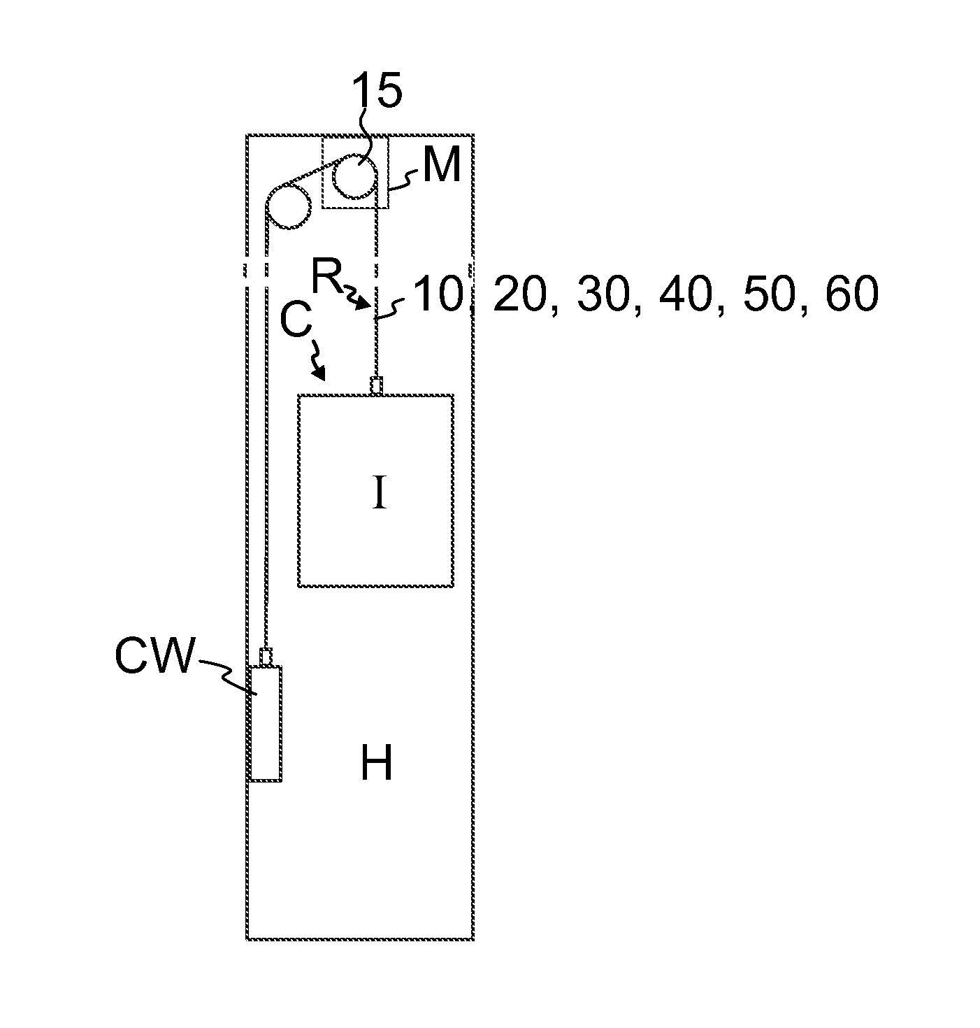
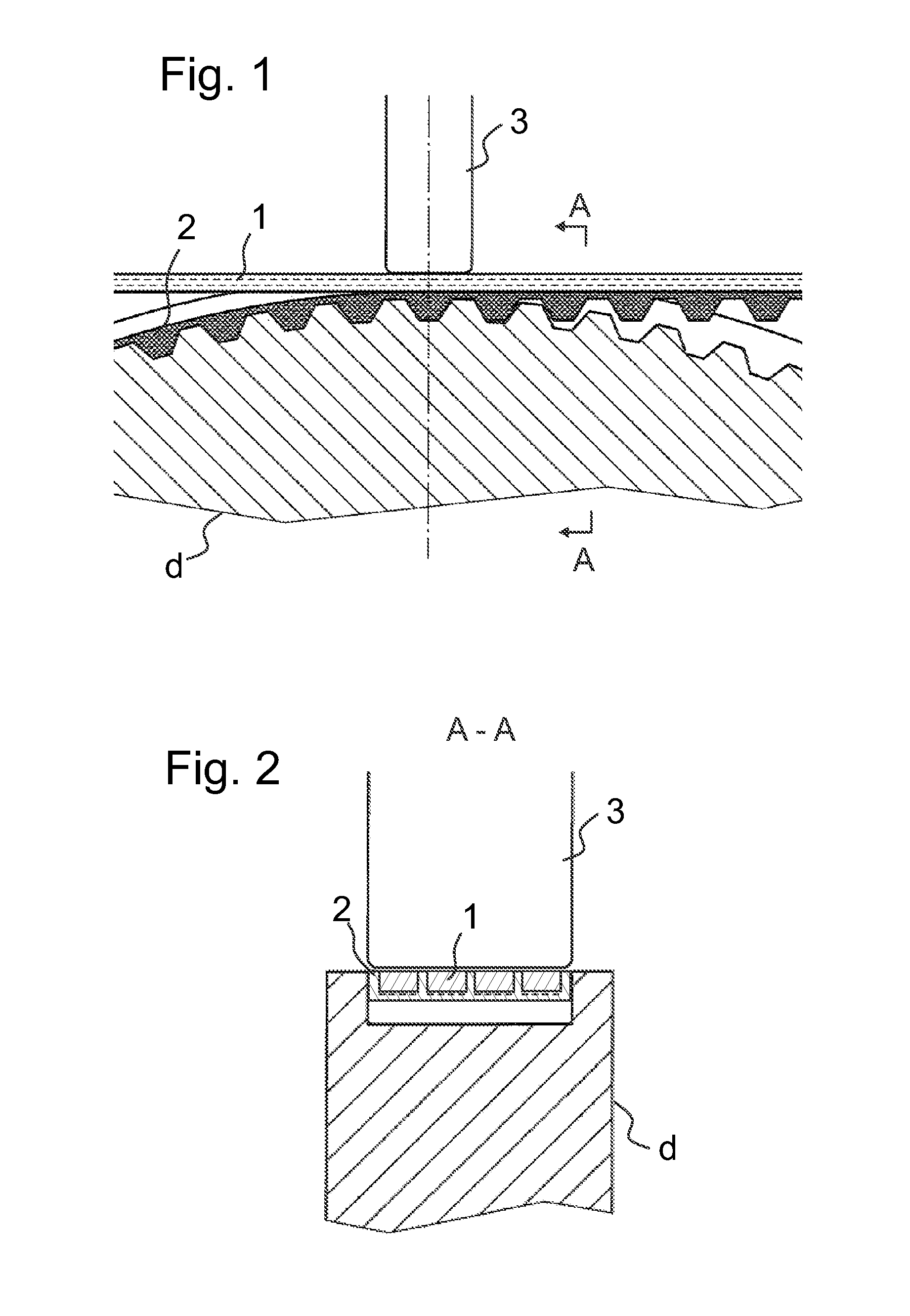
[0053]FIGS. 1 and 4 each illustrates an embodiment of a fixing step of a method for manufacturing a rope. In these Figures pre-manufactured elongated load bearing members 1, 1′ for the rope as well as a pre-manufactured elongated surface part 2, 2′ for the rope, which have earlier been pre-manufactured separately from each other, are guided together such that their lateral sides are in contact and lean against each other. After this they are fixed to each other. Thus, a rope 10, 20, 30, 40, 50, 60, as illustrated in FIGS. 9 and 12 for instance, can be manufactured simply and with a fast process. Because the load bearing members 1, 1′ and the surface part 2, 2′ are pre-manufactured, their integration to form together an integral structure is accurate, simple and quick. Both the load bearing members and the surface part have been pre-manufactured to have an optimal structure with a process of optimal speed and type for it. Thus, their manufacturing processes don't affect each other. F...


PUM

PropertyMeasurementUnit
Thicknessaaaaaaaaaa
Widthaaaaaaaaaa
Thermoplasticityaaaaaaaaaa

Abstract

A method for manufacturing a rope includes providing at least one pre-manufactured elongated load bearing member for the rope and at least one pre-manufactured elongated surface part for the rope, guiding together said at least one pre-manufactured elongated load bearing member and said at least one pre-manufactured elongated surface part such that their sides lean against each other, and fixing said at least one pre-manufactured elongated load bearing member and said at least one pre-manufactured elongated surface part to each other. A rope obtained with the method, and an elevator including the rope obtained with the method are also disclosed.

Description

FIELD OF THE INVENTION[0001]The invention relates to a method for manufacturing a rope and a rope manufactured with the method. The rope is in particular a rope of an elevator meant for transporting passengers and / or goods.BACKGROUND OF THE INVENTION[0002]Elevators typically have suspension ropes for suspending the elevator car and the counterweight. The suspension roping passes around a sheave located above the car and counterweight suspending the car and counterweight on opposite sides of the sheave. In addition to suspension function, these ropes are often used for transmitting moving force to the car and counterweight from a motor driving a sheave around which the ropes pass. In addition to said suspension ropes, elevators often also comprise a roping passing around a sheave located below the elevator car and counterweight. This roping is provided either as a compensation roping for compensating the imbalance in the suspension roping or as a lock-down-roping for keeping the car ...

Claims


Application Information

Patent Timeline
IPC IPC(8): B66B7/06B66B11/00
CPCB66B11/0065B66B7/062B29C65/086B29C66/112B29C66/1122B29C66/114B29C66/433B29C66/4332B29C66/526B29C66/69B29C66/7212B29C66/72141B29C66/7392B29C66/81431B29C66/83411B29D29/06B29L2016/00B29L2031/707D07B1/162D07B1/167D07B1/22D07B2501/2007F16G1/14F16G9/00Y10T428/2933D07B2201/2046D07B2205/2014D07B2205/205D07B2205/2096D07B2205/3003D07B2205/3007D07B2201/2016B29K2307/04B29K2309/08B29K2277/10B29K2223/0683D07B2801/10
Inventor PELTO-HUIKKO, RAIMOVALJUS, PETTERIALASENTIE, PENTTI
Owner KONE CORP
Learn More