
Self-corrugating laminates useful in the manufacture of thermoelectric devices and corrugated structures therefrom

a technology of laminates and corrugated structures, applied in the field of laminate films, can solve the problems of labor-intensive processes, limited ability to make structural or functional plastic panels, and limited process selection and selection,

Active Publication Date: 2014-10-30
EASTMAN CHEM CO
View PDF2 Cites 42 Cited by
  • Summary
  • Abstract
  • Description
  • Claims
  • Application Information

AI Technical Summary

Benefits of technology

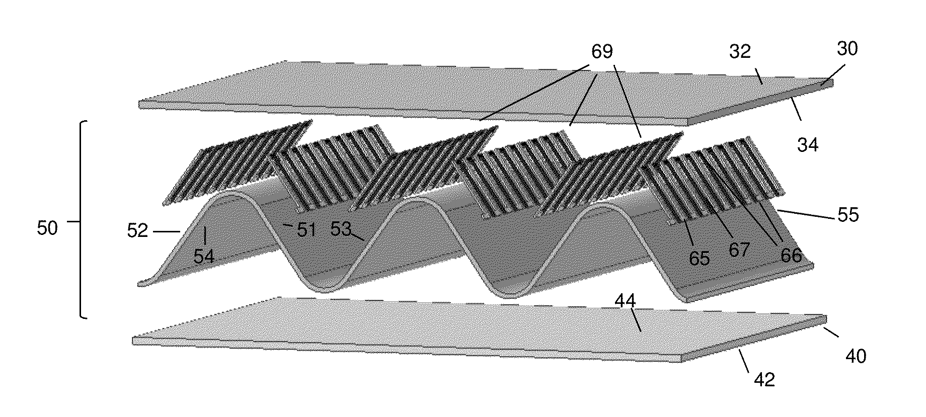
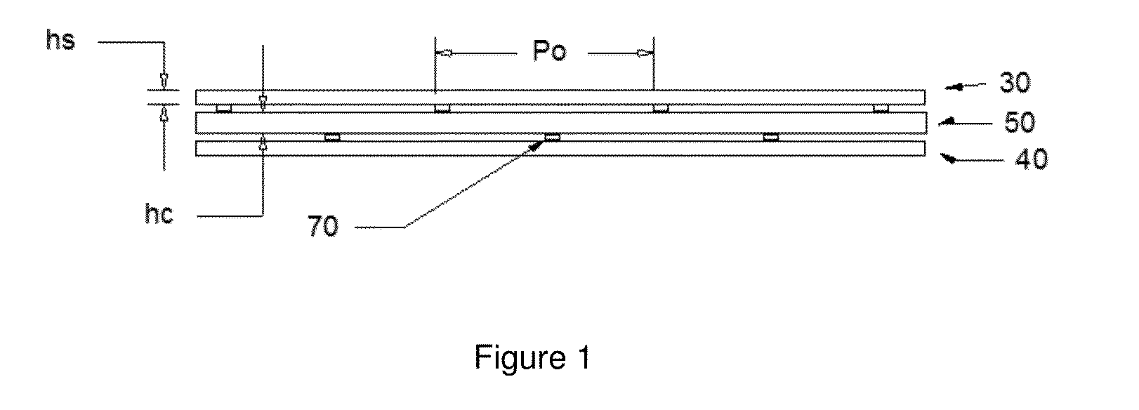
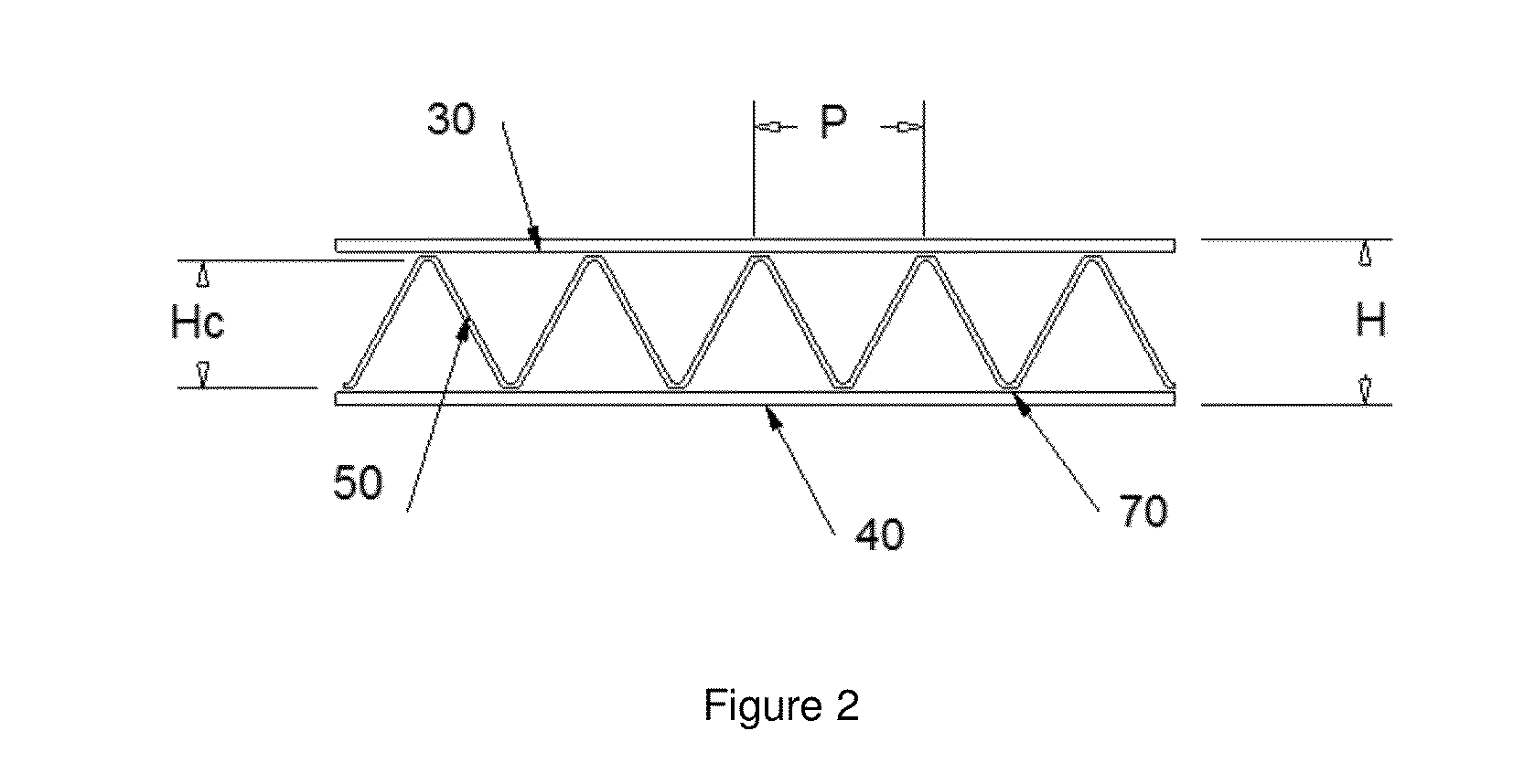
The invention is about self-corrugating laminates that can be used in the manufacture of thermoelectric devices or modules. These laminates have a non-shrinkable core that is bonded between two shrinkable film layers using bond lines. The shrinkable film layers have a percentage shrinkage of 10-45 when heated, and the bond lines are staggered to create structural corrugations in the non-shrinkable core. The laminates also have a corrugation ratio of 0.1-0.9 and an aspect ratio of 0.1-0.8. The bond lines can be formed using adhesive, conductive adhesive, heat-weld, or solvent-weld. The resulting structure has a thickness that differs due to differences in the bond line spacing. The non-shrinkable core film layer is formed from two non-shrinkable film layers adhered to one another with a shrinkable film layer bonded between them using bond lines.

Problems solved by technology

The ability to make structural or functional plastic panels is limited to just a few processes because of the low modulus of plastics in general, coupled with the difficulty of generating three-dimensionally-reinforced structures.
The processes that are available are either labor-intensive (e.g. thermoforming and bonding) or require extensive tooling (e.g. twin wall sheet extrusion).
Parts made by these methods are also typically limited to two-dimensions such as with panels and, once produced, tend to be bulky and cannot be easily shipped or packaged.
It is also difficult to introduce functionality into these structures because the core material is not easily modified, being specific to the intended use.
Although prior art constructions are known in which shrinkable layers assist in forming corrugations, we have found conventional shrinkable materials unsuitable to more demanding applications in which regular, structural corrugations are required.
The contractable lamina, which may contract as much as 50 to 70 percent of its original stretched dimensions upon activation, is said to be sharply corrugated, resulting in a lack of structural rigidity needed for more demanding applications.
Being on the low side of this range means the shrink force is too high relative to the buckling resistance of the core such that overbuckling / wrinkling typically occurs.

Method used


Image

  • Self-corrugating laminates useful in the manufacture of thermoelectric devices and corrugated structures therefrom
  • Self-corrugating laminates useful in the manufacture of thermoelectric devices and corrugated structures therefrom
  • Self-corrugating laminates useful in the manufacture of thermoelectric devices and corrugated structures therefrom

Examples


examples

[0114]The following experimental methods were used to characterize the films and corrugated structures.

[0115]Shrinkage was determined by immersing a 100 mm×100 mm sample of the shrink film sample in water at 95° C. Hot water was used because copolyester shrink films (Tg=72° C.) were used for the experiments. Film was held in the bath for at least 30 seconds to ensure full shrinkage was complete. The length of the sample was then measured and the shrinkage in each direction determined by the following formula:

Percent shrinkage=(Lo−L) / Lo*100  (1)

in which L is the length after shrinkage and Lo is the initial length (100 mm). For shrink films having a Tg>100° C., hot water can no longer be used, so either hot oil or hot air is required. For these tests, the temperature of shrinkage should be at least Tg+20° C. and the sample held until full shrinkage is acquired. This is typically about 30 seconds for liquid media and 1 minute for hot air ovens.

[0116]Shrink stress was measured in a simi...

examples 1-10

Corrugated Structures with Polycarbonate Core

[0124]For these examples, a series of uniaxially stretched films were bonded to a polycarbonate film core using a UV adhesive (Dymax SC330 gel). The copolyester shrink layer comprised Eastman Embrace LV™ (Eastman Chemical Company, Kingsport, Tenn.), a material commonly used for shrink film packaging (Tg=72° C.). To make the shrink film, a cast film 0.25 mm thick was extruded to create the unoriented base material. This film was then stretched on a Bruckner laboratory film stretcher at a nominal temperature of 82° C. Stretch ratio was varied from 1.25× up to 2× which yielded films having shrinkage from about 20% up to 50% (see Table I).

[0125]Next these shrink films were cut into 1 inch (25.4 mm) wide strips and then bonded to 25.4 mm wide strips of polycarbonate (core) film using the UV curable adhesive. Small stripes of adhesive were painted onto one side of the core at fixed intervals (Po was either 19 mm, 25.4 mm or 38 mm depending on t...

examples 11-15

Corrugated Structures with Copolyester

[0129]These examples followed the same procedure as with Example 1, except that the core was made from Eastman Tritan™ high Tg copolyester (nominal Tg=120° C.). As with the previous examples poor corrugation resulted because either the film shrinkage was too high, or the corrugation ratio was out of the desired range. Samples with corrugation ratio greater than 1 would not corrugate at all, whereas the very low corrugation ratios would result in excessive wrinkling.


PUM

PropertyMeasurementUnit
shrinkageaaaaaaaaaa
shrinkageaaaaaaaaaa
shrinkageaaaaaaaaaa

Abstract

Self-corrugating laminates useful in the manufacture of thermoelectric devices are disclosed. The laminates include an upper and a lower shrinkable film layer and a non-shrinkable core with a thermoelectric pattern formed thereon bonded between said upper and lower shrinkable film along bond lines arranged parallel, substantially parallel, radially, or annularly. The bond lines that bond the upper shrinkable film layer to top surface of the nonshrinkable core are staggered relative to the bond lines that bond the lower shrinkable film layer to the bottom surface of the non-shrinkable core such that upon shrinkage of the shrinkable film layers, structural corrugations are formed in the non-shrinkable core. Thermoelectric modules or devices and methods for forming them from the self-corrugating laminates are also described.

Description

CROSS REFERENCE TO RELATED APPLICATIONS[0001]This application claims the benefit of U.S. Provisional Application No. 61 / 816,234 filed Apr. 26, 2013, the entirety of which is hereby incorporated by reference.FIELD OF THE INVENTION[0002]The present invention relates to laminate films, and specifically, to self-corrugating laminates that are useful in the manufacture of thermoelectric devices.BACKGROUND OF THE INVENTION[0003]The ability to make structural or functional plastic panels is limited to just a few processes because of the low modulus of plastics in general, coupled with the difficulty of generating three-dimensionally-reinforced structures. The processes that are available are either labor-intensive (e.g. thermoforming and bonding) or require extensive tooling (e.g. twin wall sheet extrusion). Parts made by these methods are also typically limited to two-dimensions such as with panels and, once produced, tend to be bulky and cannot be easily shipped or packaged. It is also d...

Claims


Application Information

Patent Timeline
Patent Type & Authority Applications(United States)
IPC IPC(8): H01L35/04B29C61/02H01L35/34H10N10/10H10N10/01H10N10/81H10N10/13H10N10/17
CPCH01L35/04H01L35/34B29C61/02B32B3/28B32B2307/302H10N10/13H10N10/01H10N10/17H10N10/81F25B21/02
Inventor SHELBY, MARCUS DAVIDCALVERT, DAVID B.WILLIAMS, FREDDIE WAYNECLEAR, SCOTT ALLENMACKENZIE, PETER BORDENTANNER, CANDACE MICHELESTIKELEATHER-PEAVEY, JENNIFER LYNNEOWENS, JEFFREY TODD
Owner EASTMAN CHEM CO
Learn More