
Inter-image prediction method and device and corresponding coding method and apparatus

a prediction method and image technology, applied in the field of image coding, can solve the problems of large number of bits for coding this prediction error, and the cost of coding the syntax elements required by the remote decoder to reconstruct the predicted image is relatively high, so as to achieve the effect of reducing the cost of coding

Inactive Publication Date: 2014-10-23
INTERDIGITAL VC HLDG INC
View PDF9 Cites 5 Cited by
  • Summary
  • Abstract
  • Description
  • Claims
  • Application Information

AI Technical Summary

Benefits of technology

The purpose of this invention is to save money on coding information used in a temporal prediction method. The invention does this by using a reduced number of patches to define the first patch of the dictionary, which results in a lower coding cost compared to the standard method.

Problems solved by technology

In fact, if the contents of the current block and the prediction block are very different, the prediction error will be significant which will lead to a significant number of bits for coding this prediction error.
Moreover, in a context of transmission between a transmitter and a receiver, the cost of coding the syntax elements required by the remote decoder to reconstruct a predicted image is relatively high.

Method used


Image

  • Inter-image prediction method and device and corresponding coding method and apparatus
  • Inter-image prediction method and device and corresponding coding method and apparatus
  • Inter-image prediction method and device and corresponding coding method and apparatus

Examples


Embodiment Construction

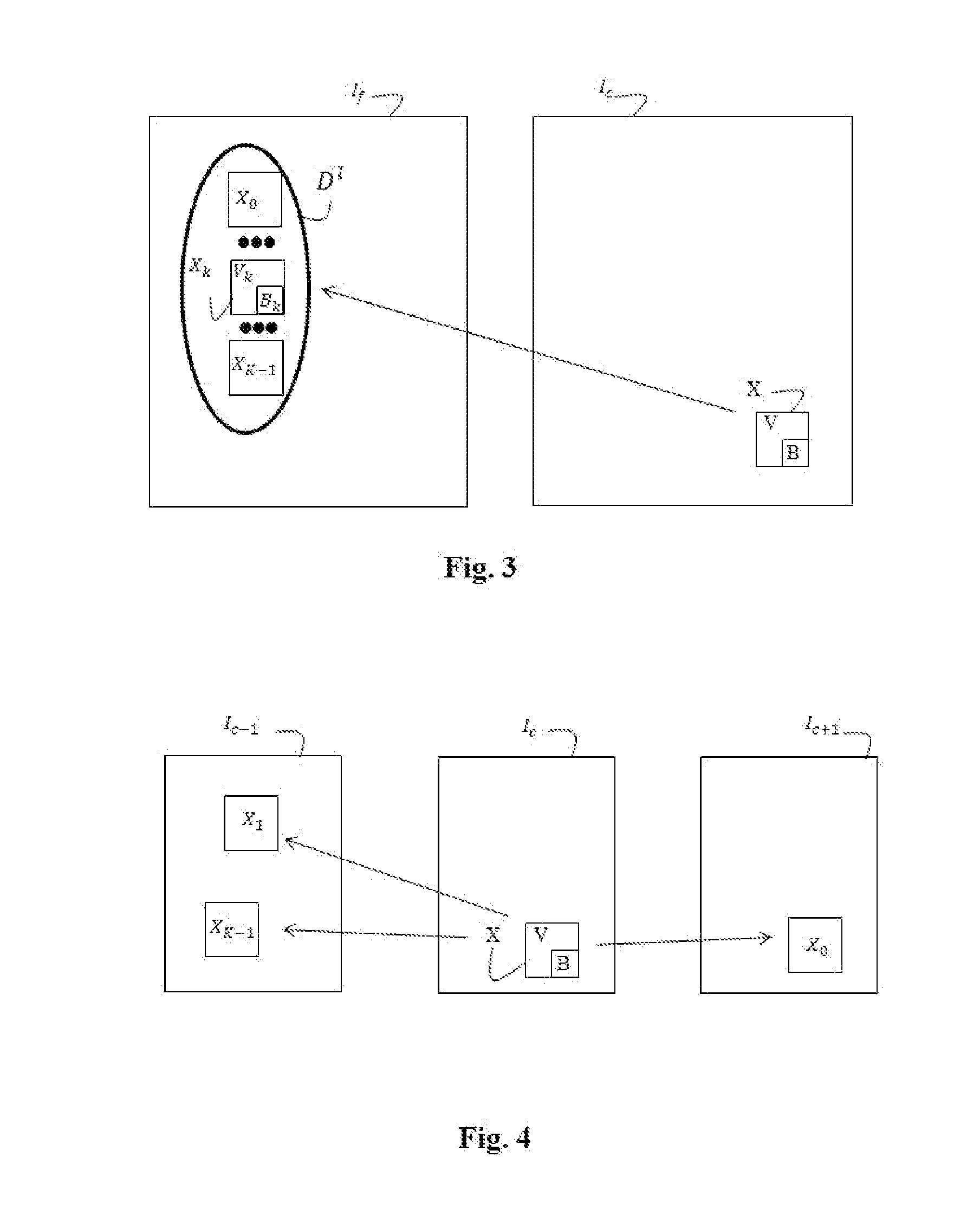
[0036]Hereafter, the term patch, denoted Xk, will be used to designate a grouping of pixels of a block Bk and pixels of a neighbourhood Vk of this block Bk. The neighbourhood Vk is causal of this block Bk and has an identical form to that of a neighbourhood V situated around a pixel block B to be predicted. The causality of a neighbourhood with respect to a pixel block indicates that the pixel values are known prior to the prediction of this block. The patch X is also used hereafter to designate the grouping of pixels of the pixel block to be predicted B and pixels of the neighbourhood V.

[0037]FIG. 1 gives an example of defining a causal neighbourhood. According to this example, the neighbourhood V is formed, for example, of three blocks situated to the left and above the pixel block B to be predicted. A neighbourhood is a vector of N values, each value corresponding to the value of a pixel belonging to this neighbourhood. The invention is in no way limited to this definition of nei...


PUM


Abstract

The invention relates to a method for predicting a pixel block of an image using a weighted sum of pixel blocks belonging to patches of a dictionary from a set of candidate patches, each patch being formed of a pixel block of an image and a causal neighborhood of this pixel block. The method is wherein a subset of candidate patches is obtained from the set of candidate patches and the dictionary is formed of a patch of the subset of candidate patches, called the first patch, and at least one other patch of said set of candidate patches, called the second patch.

Description

1. FIELD OF THE INVENTION[0001]The invention relates to the general field of image coding and more specifically to that of inter-image prediction.2. PRIOR ART[0002]Inter-image prediction consists in taking advantage of the temporal redundancies which exist between consecutive images of a video in order to obtain high compression rates for this video.[0003]The principle of inter-image prediction consists in dividing a current image into blocks or macroblocks. Then, the coder finds a similar block in another (previous or future) image of the video. This other image is usually called the reference image. The coder then encodes a motion vector which defines the position of the block found in said reference image(s) from the block to be predicted. The coder then calculates the difference between these two blocks and codes the prediction error. The motion vector and the prediction error are then transmitted to the decoder which can thus reconstruct the block.[0004]A great many video codin...

Claims


Application Information

Patent Timeline
Patent Type & Authority Applications(United States)
IPC IPC(8): G06T9/00
CPCG06T9/00H04N19/105H04N19/176H04N19/61H04N19/593H04N19/136
Inventor CHERIGUI, SAFAMARTIN, ALAINTHOREAU, DOMINIQUEGUILLOTEL, PHILIPPEGUILLEMOT, CHRISTINE
Owner INTERDIGITAL VC HLDG INC
Learn More