
Optical stack with asymmetric diffuser

Active Publication Date: 2014-09-25
3M INNOVATIVE PROPERTIES CO
View PDF4 Cites 3 Cited by
  • Summary
  • Abstract
  • Description
  • Claims
  • Application Information

AI Technical Summary

Benefits of technology

The patent text describes optical stacks and displays that have improved performance compared to previous versions. These improvements come by using an asymmetric diffuser that reduces optical defects such as moire while maintaining high contrast and optical gain. Overall, these advancements make the display look better and be easier to use.

Problems solved by technology

For example, prior displays suffered from undesirable defects such as moire and other optical defects.
Prior attempts to hide these undesirable defects resulted in a reduced optical gain and reduced contrast in the display.

Method used


Image

  • Optical stack with asymmetric diffuser
  • Optical stack with asymmetric diffuser
  • Optical stack with asymmetric diffuser

Examples


example 1

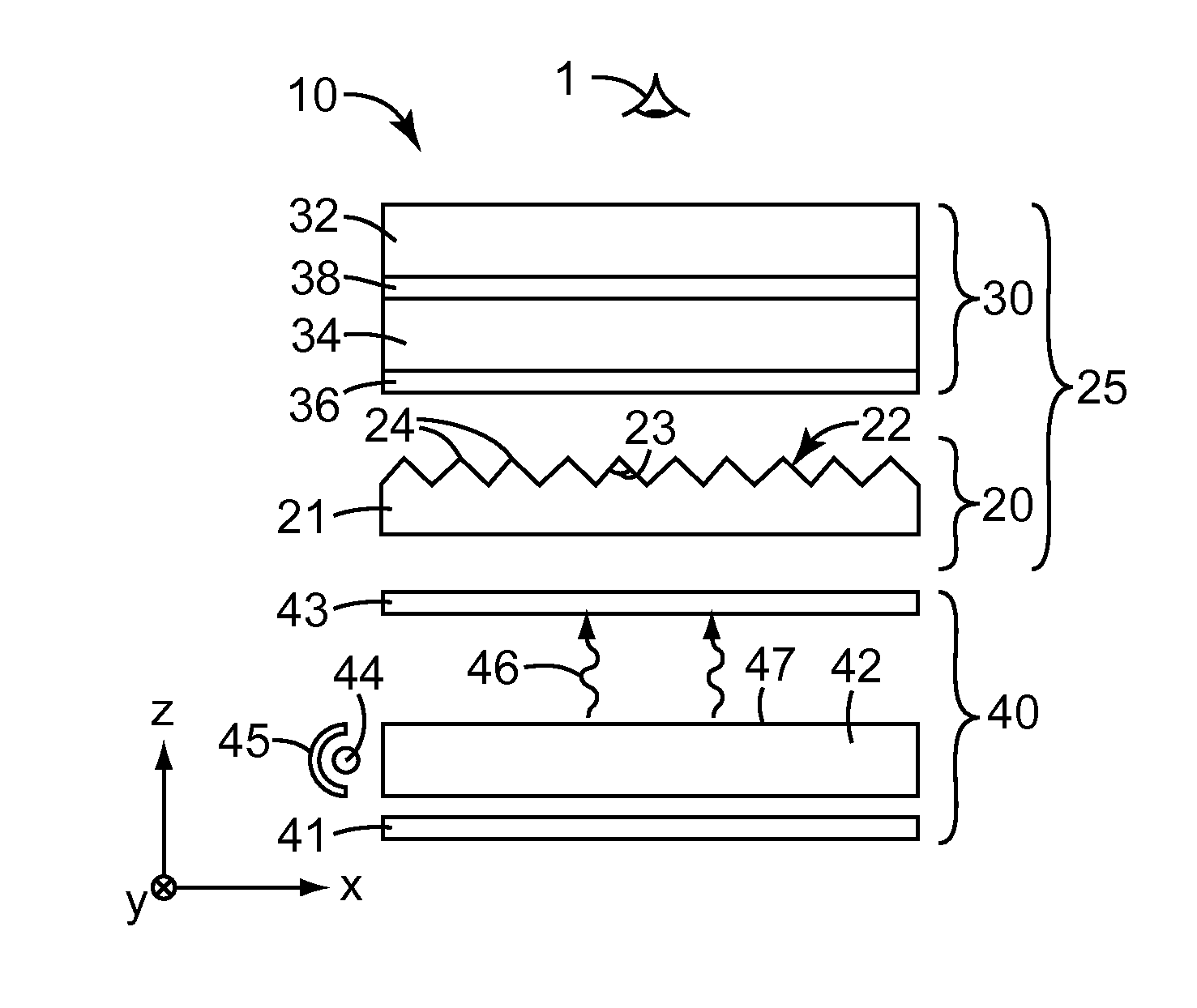
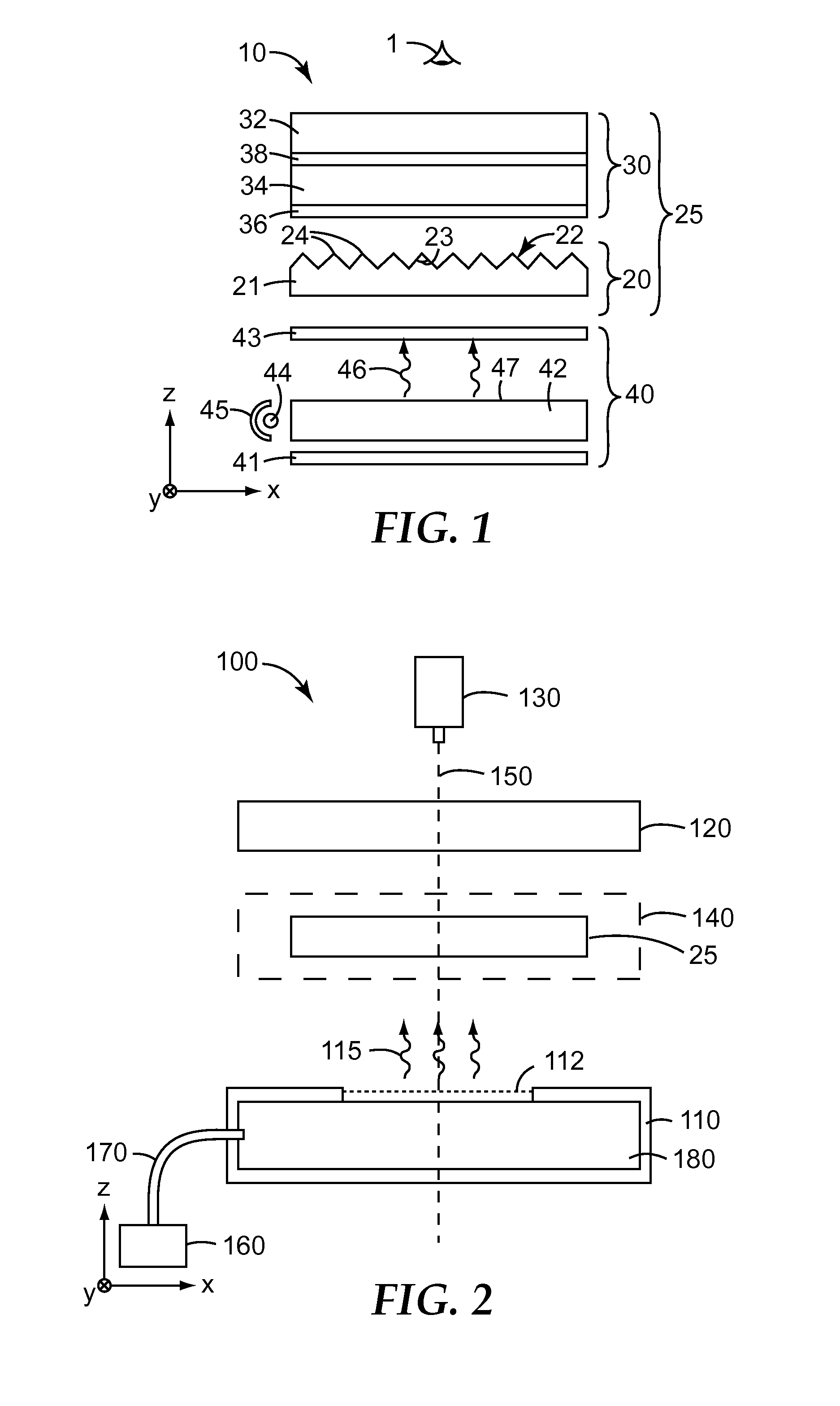
[0040]An optical stack was assembled as follows. An LCD panel was obtained from a Sony NSX-32GT1 television set (available from Sony USA, New York N.Y.). A sheet of reflective polarizer (DBEF-Q, available from 3M Company, St. Paul Minn.) was laminated to the underside of the panel using an optically clear adhesive (available as OCA 8171 from 3M Company) with the pass axis of the polarizer oriented along the horizontal direction of the LCD panel. Formed on the side of reflective polarizer sheet facing away from the LCD panel was an asymmetric diffuser that is described in greater detail below; this asymmetric diffuser had parallel sets of structures, each structure with the approximate shape of an elongated ellipse. The asymmetric diffuser was oriented so that the long axes of the ellipses were parallel to the pass axis of the reflective polarizer; oriented in this way, the direction of maximum diffusion was vertical, perpendicular to the pass axis. Beneath the reflective polarizer s...

example 2

[0044]An optical stack was assembled as in Example 1, except that the asymmetric diffuser structures were formed perpendicular to their direction in that example, so that they were approximately perpendicular to the prisms. In this orientation, the direction of the maximum diffusion was horizontal.

[0045]The luminance (effective transmission) of the display as a function of vertical polar angle was measured as described in Example 1. The resulting data are shown in the plot of FIG. 4.

example 3

[0046]An optical stack was assembled as in Example 1, except that the reflective polarizer film with asymmetric diffuser was replaced by a reflective polarizer with no diffuser (DBEF-Q, available from 3M Company).

[0047]The luminance (effective transmission) of the display as a function of vertical polar angle was measured as described in Example 1. The resulting data are shown in the plot of FIG. 4.


PUM


Abstract

The present disclosure describes an optical stack that includes an asymmetric diffuser. As described herein, use of an asymmetric diffuser in an optical stack reduces undesirable defects in a display while maintaining optical gain and / or contrast of the display. The asymmetric diffuser is less diffusive along a first direction that is parallel with linearly extending structures of an associated light directing film

Description

FIELD[0001]The present disclosure relates to, among other things, an optical display that includes an asymmetric diffuser.BACKGROUND[0002]Display systems, such as liquid crystal display (LCD) systems, are used in a variety of applications and commercially available devices such as, for example, computer monitors, personal digital assistants (PDAs), mobile phones, miniature music players, and thin LCD televisions. Many LCDs include a liquid crystal panel and an extended area light source, often referred to as a backlight, for illuminating the liquid crystal panel. Backlights can include one or more lamps and a number of light management films.BRIEF SUMMARY[0003]The present disclosure describes an optical stack that includes an asymmetric diffuser, among other aspects.[0004]In many embodiments, an optical stack is described. The optical stack includes a first optical stack and a second optical stack disposed on the first optical stack. The first optical stack includes a light directin...

Claims


Application Information

Patent Timeline
IPC IPC(8): G02F1/1335
CPCG02F1/133504G02F2001/133607G02F1/133606G02F1/133536G02F1/133607
Inventor HAAG, ADAM D.PHAM, TRI D.KONG, STEVEN H.C.ETZKORN, STEPHEN J.ENDRES, ROBERT L.JOHNSON, MATTHEW B.
Owner 3M INNOVATIVE PROPERTIES CO
Learn More