
MRI safety device means and methods thereof

a safety device and mri technology, applied in the field of imaging procedures, can solve the problems of physical danger to patients, difficult to remove objects from the interior of the mri, and the magnetic fringing field, and achieve the effect of increasing the distance (l) from the apertur

Active Publication Date: 2014-09-18
ASPECT IMAGING
View PDF7 Cites 61 Cited by
  • Summary
  • Abstract
  • Description
  • Claims
  • Application Information

AI Technical Summary

Benefits of technology

The present invention relates to a system for magnetic shielding in magnetic resonance imaging (MRI) devices. The system includes a magnet that creates a magnetic field to shield the MRI device from metallic objects that may enter through an aperture. The magnet is placed at a distance from the MRI device's aperture and its magnetic field is directed towards the MRI device's open bore. The system can be used in a variety of ways, such as in a horizontal patient bed or a gantry, and can be portable. The technical effects of the invention include reducing the risk of metallic objects entering the MRI device and improving the quality of MRI images.

Problems solved by technology

If the object is in the vicinity of the MRI's opening, such as an opening to allow entrance of a subject to be analyzed, the object can become very difficult to remove from the interior of the MRI.
Worse, in an MRI located within the hospital, for imaging patients, such a magnetic fringing field can be physically dangerous to the patient, if not fatal.

Method used


Image

  • MRI safety device means and methods thereof
  • MRI safety device means and methods thereof
  • MRI safety device means and methods thereof

Examples


Embodiment Construction

[0035]The following description is provided, alongside all chapters of the present invention, so as to enable any person skilled in the art to make use of the invention and sets forth the best modes contemplated by the inventor of carrying out this invention. Various modifications, however, will remain apparent to those skilled in the art, since the generic principles of the present invention have been defined specifically to provide a means and method for avoiding penetration of metallic objects throughout an aperture, towards the open bore of an MRI device.

[0036]The term “metallic objects” refers hereinafter to any metal that produces a magnetic field in response to an applied magnetic field such as ferromagnetic and ferrimagnetic metals.

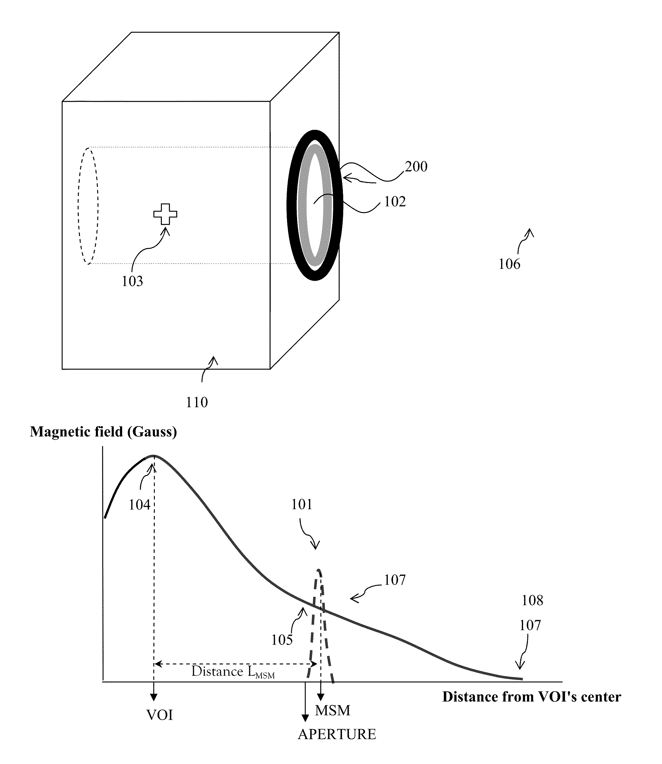
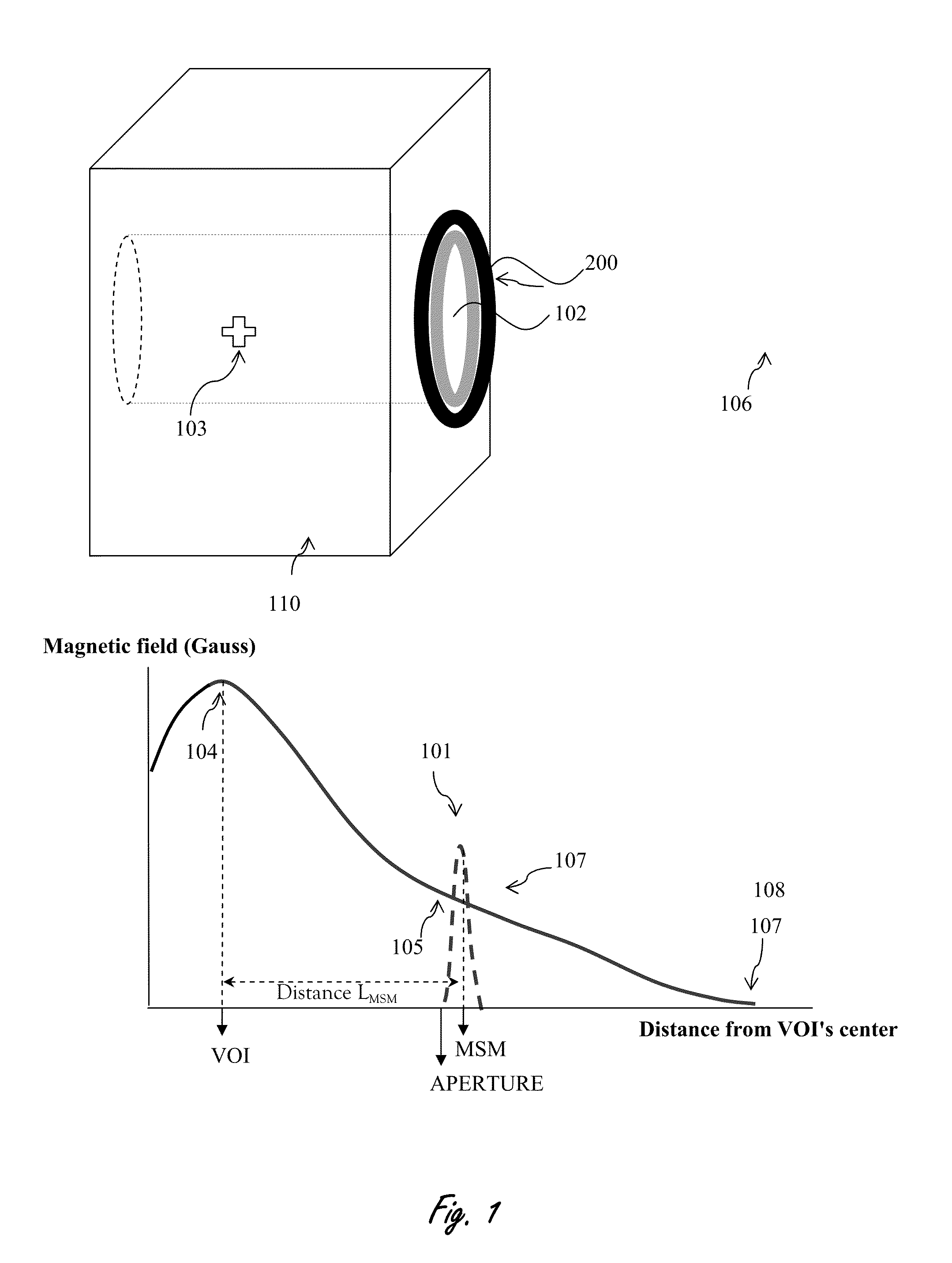
[0037]Reference is made now to FIG. 1, illustrating (see upper figure) a schematic cross section (side view) of an MRI device (110) having an open bore with a volume of interest (103) where maximal magnetic field is applied. The bore has an apertu...


PUM


Abstract

A magnetic shielding mechanism for preventing penetration of metallic objects through an aperture, towards the open bore of an magnetic resonance imaging device, where the magnetic field is maximized. The magnetic resonance imaging device produces a fringing magnetic field that decreases with increasing distance (L) from the aperture. The mechanism includes at least one magnet with a magnetic field. The mechanism is affixed at a distance from the aperture of magnetic resonance imaging device.

Description

FIELD OF THE INVENTION[0001]The present invention pertains to safety during imaging procedures related to magnetic fields and more particularly to protection of personnel and equipment involved in MRI diagnosis.BACKGROUND OF THE INVENTION[0002]In general, the static magnetic fields in MRI systems may be more than about 0.5 T; some such systems have static magnetic fields greater than 3 T. These magnetic fields will attract metal objects in the vicinity of the static magnets. If the object is in the vicinity of the MRI's opening, such as an opening to allow entrance of a subject to be analyzed, the object can become very difficult to remove from the interior of the MRI. Worse, in an MRI located within the hospital, for imaging patients, such a magnetic fringing field can be physically dangerous to the patient, if not fatal.[0003]Fringe fields from a high field strength can extend to a distance determines roughly by the equation X=αβ0, where α is a constant dependent on the magnet bor...

Claims


Application Information

Patent Timeline
IPC IPC(8): G01R33/421
CPCG01R33/288G01R33/4215G01R33/30
Inventor RAPOPORT, URI
Owner ASPECT IMAGING
Learn More