
Portable adjustable multiple end drill device

Active Publication Date: 2014-09-11
DIAMOND BENJAMIN
View PDF3 Cites 7 Cited by
  • Summary
  • Abstract
  • Description
  • Claims
  • Application Information

AI Technical Summary

Benefits of technology

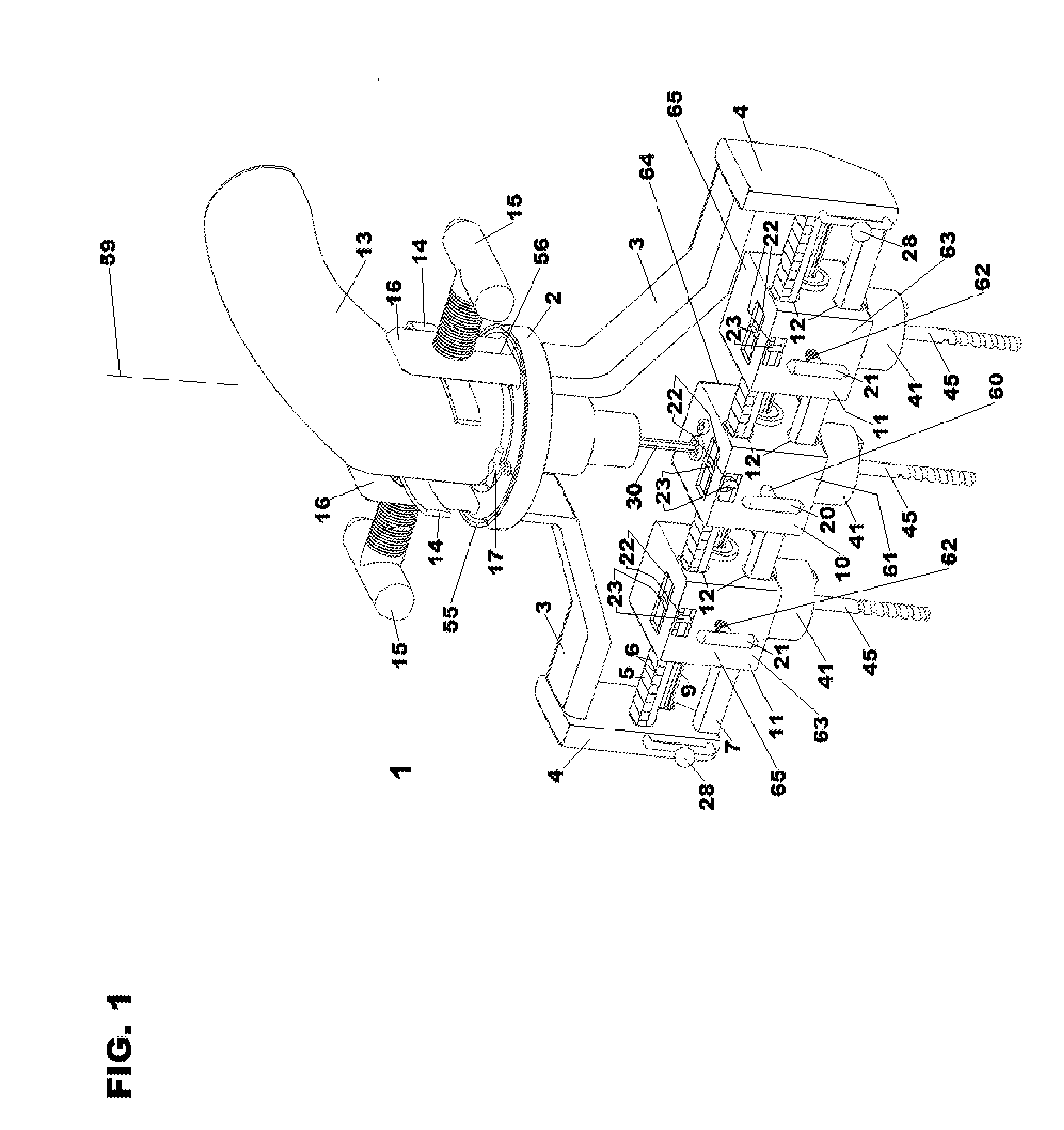
The present invention is a portable device that can drill multiple straight holes or attach multiple straight fasteners. It features multiple end drill units that can be moved and secured to any position along guide bars with minimal restrictions. The device is powered by a hand-screwed input drill, which is connected to the main end drill unit through an input shaft and gears. The spline shaft allows for simultaneous rotation of all drill bits and fastener bits being used. The device is convenient and easy to adjust the positions of the end drill units.

Problems solved by technology

However, such configurations only allow one drill bit to be used at a time.
However, a disadvantage with this configuration is that distances between all holes must still be manually measured and locations marked using a measuring device and writing utensil.
Another disadvantage is that the amount by which the spacing between drill or fastener bits may be adjusted is limited.
A further disadvantage is that the operator must hold a multiple-bit drill in place with at least one of his / her hands throughout the entire drilling or driving process, as well as the electric drill supplying power to the multiple-bit drill.
Moreover, larger units for drilling holes or fastening fasteners that are at great distances from one another require a large number of moving parts, several of which may not even be used in such situations.
Additionally, parts that are not heir used cannot be easily removed.
Many gears, pivot arms, and chucks are permanently or semi-permanently attached to the multi-bit drill and are not meant to be easily removed when not in use.

Method used


Image

  • Portable adjustable multiple end drill device
  • Portable adjustable multiple end drill device
  • Portable adjustable multiple end drill device

Examples


Embodiment Construction

[0016]Before any embodiments of the invention are explained in detail, it is to be understood that the invention is not limited in its application to the details of construction and the arrangement of components set forth in the following description or illustrated in the following drawings. The invention is capable of other embodiments and of being practiced or of being carried out in various ways. Also, it is to be understood that the phraseology and terminology used herein is for the purpose of description and should not be regarded as limiting. The use of “including,”“comprising,” or “having” and variations thereof herein is meant to encompass the items listed thereafter and equivalents thereof as well as additional items. Unless specified or limited otherwise, the terms “mounted,”“connected,”“supported,” and “coupled” and variations thereof are used broadly and encompass direct and indirect mountings, connections, supports, and couplings. Further, “connected” and “coupled” are ...


PUM

PropertyMeasurementUnit
Forceaaaaaaaaaa
Poweraaaaaaaaaa

Abstract

A portable adjustable multiple end drill device comprises a rotary power source communicating with a plurality of end drill units. The device includes restraints for holding the rotary power source and a hearing rigidly attached to the restraints for rotating the device. The device includes two end-caps, each of which is connected to a respective arm directly or via at least one modular extension of a respective arm. The end-caps are also connected to guide bars and a splined power transmission shaft. The device imparts a set of rectilinearly aligned work areas of a work piece, which work areas are respectively and simultaneously drilled by the respective drill bits. A rectilinear position of each end drill unit can be adjusted mechanically. Each drill bit holder, or base, holding a respective drill bit or fastener bit is rotated by a system of bearing-journaled drive gears.

Description

FIELD OF THE INVENTION[0001]The present invention relates to portable adjustable multiple end drill devices for simultaneously drilling a plurality of rectilinearly aligned holes or fastening a plurality of rectilinearly aligned fasteners.BACKGROUND OF THE INVENTION[0002]It is desirable to expand the drilling capability of a hand-held electric drill. In one known configuration, an electric hand-held drill includes an internal magazine that stores a plurality of drill bits. However, such configurations only allow one drill bit to be used at a time. In another configuration, a turret is used that contains a plurality of chucks. While this configuration is able to hold a plurality of drill bits or fastener bits simultaneously, only one bit can be used at a time to drill a hole or fasten a fastener. In particular, when one drill bit or fastener bit and its chuck are in use, the other drill bits or fastener bits and chucks are stationary. In a further configuration, an operator is able t...

Claims


Application Information

Patent Timeline
IPC IPC(8): B23B39/18B23P11/00B23B39/16
CPCB23B39/18B23P11/00B23B39/162B23B2260/004Y10T29/49895Y10T408/21Y10T408/655
Inventor DIAMOND, BENJAMINSADEGH, ALI M.
Owner DIAMOND BENJAMIN
Learn More