
Locking suture

a self-locking, suture technology, applied in the field of surgical suture materials, can solve the problems of infection, other complications, and difficulty in knotting procedure, and achieve the effect of improving the stability of the suture, and improving the suture stability

Active Publication Date: 2014-09-04
KENT ISLAND HLDG
View PDF10 Cites 2 Cited by
  • Summary
  • Abstract
  • Description
  • Claims
  • Application Information

AI Technical Summary

Benefits of technology

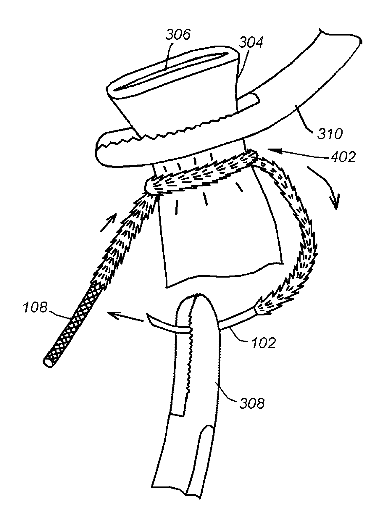
The invention provides a suture system and method that can be secured without knots. A locking suture is used that includes a needle and a thread with barbs arranged in rows. The barbs are biased open and can splay against the outer surface of the thread for a locking effect. The needle is applied over the end of the thread using conventional methods, such as adhesive, welding, or crimping. The thread can be braided at the terminal end. The suture is wrapped around the vessel multiple times until the desired number of wraps is achieved, and then the needle is driven through the terminal end and pulled back until all the slack is passed. A reverse tension force is applied to create the locking structure. The plurality of barbs lies flat during the drawing through the suture. The locking suture system provides a way to securely close a vessel without a knot.

Problems solved by technology

The application of a ligation during endoscopic surgery or surgery in a tight area can create difficulties for the knotting procedure.
This procedure is typically performed under cramped conditions that can make the knotting process difficult.
The use of clips in place of knotted sutures is popular, but leaving a device within a body, even a dissolvable device, can cause secondary issues, such as infections, and other complications.

Method used


Image

  • Locking suture
  • Locking suture
  • Locking suture

Examples


Embodiment Construction

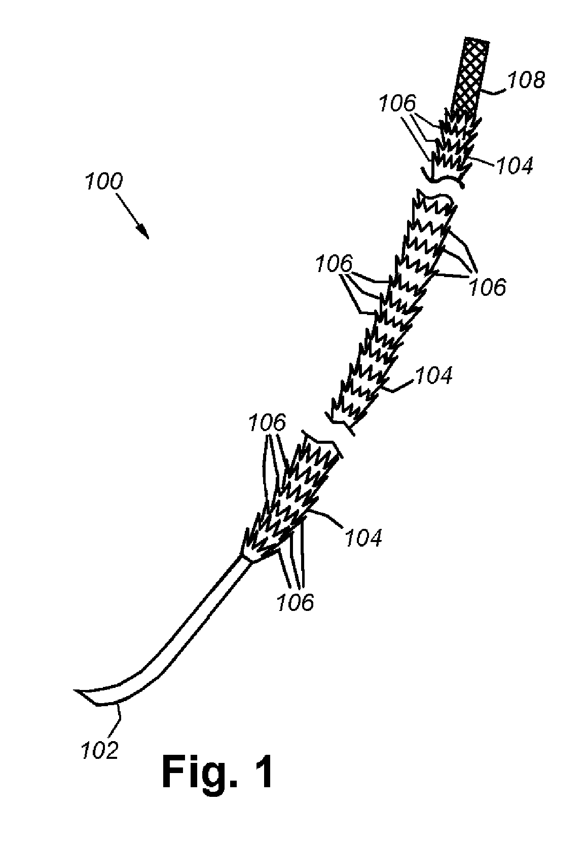
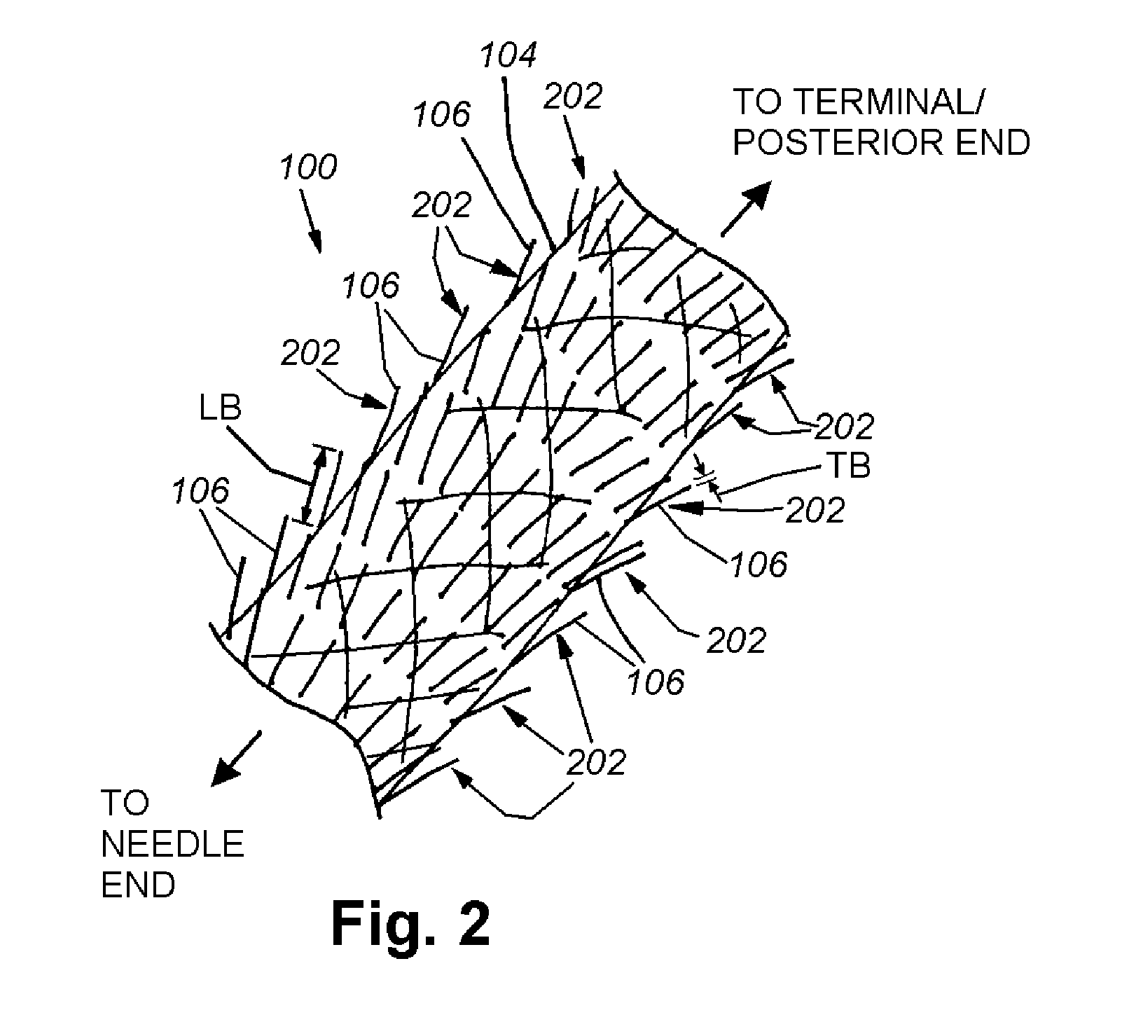
[0025]FIG. 1 depicts a locking suture 100 that is provided with a needle 102 and a woven thread 104 that is constructed and arranged with a plurality of locking barbs 106 and a braided terminal end 108. The barbs 106 are constructed and arranged to project outwardly away from the needle end and are in one or more successive circumferential rows forming the outer covering of the thread. The rows can be of a regular order, where each row of barbs 106 is aligned with the previous and following row, or an irregular order, where each row of barbs 106 is not aligned with the previous or following rows. The rows can be disposed at regular intervals. The barbs 106 are oriented so that they are uniformly feathered, being closed in the direction of the needle and open toward the terminal (posterior) end. The barbs are constructed so as to naturally be bias open in an “open” configuration when not in use and arranged to resist pull out when passed through the thread. The feathering provides fo...


PUM


Abstract

This invention provides a suture system and method that does not require knots. A locking suture includes a needle and a thread that is provided with a plurality of locking barbs. The needle is applied over an end of the thread by conventional systems. The exterior surface of the thread is covered with barbs. The barbs can be arranged in rows of at least one barb each, circumscribing the thread of the suture and are oriented so that they are uniformly feathered, being closed in the direction of the needle and open toward the terminal (posterior) end. The feathering provides for the barbs to lie flat when drawn through a membrane or other material, and the bias causes them to splay open when a tension towards the terminal / posterior end is exerted. This splaying creates a locking force.

Description

RELATED APPLICATIONS[0001]This application claims the benefit of U.S. Provisional Application Ser. No. 61 / 771,433, filed Mar. 1, 2013, entitled LOCKING SUTURE, the entire disclosure of which is herein incorporated by reference.FIELD OF THE INVENTION[0002]The present invention relates to surgical suture materials, and more particularly, to a suture is self-locked.BACKGROUND OF THE INVENTION[0003]Ligation is a process of binding vessels (e.g., arteries, veins, fallopian tubes, testicular tubes and the like) using a suture, a mechanical clamp or another binding system. When a suture is used to perform a ligation, the surgeon secures it with a knot. The application of a ligation during endoscopic surgery or surgery in a tight area can create difficulties for the knotting procedure.[0004]Surgical sutures consist of a needle and thread. The needles can be straight or curved. The curvature can describe up to ⅝ths of a circle. Most modern sutures are synthetic, including the absorbables pol...

Claims


Application Information

Patent Timeline
IPC IPC(8): A61B17/04
CPCA61B17/0482A61B17/0483A61B17/0487A61B17/06A61B17/062A61B2017/0496A61B2017/06176
Inventor BUNGE, FREDERICK ARNOLD
Owner KENT ISLAND HLDG
Learn More