
Telemetry system with tracking receiver devices

a receiver device and telemetry technology, applied in the field of wireless charging, can solve the problems of unintentional radiation interference with other systems, difficult charging over reasonable distances (e.g., less than 1 to 2 meters), and unwieldy wired configuration, etc., to achieve the effect of improving wireless power transmission

Active Publication Date: 2014-09-04
FITBIT INC
View PDF2 Cites 267 Cited by
  • Summary
  • Abstract
  • Description
  • Claims
  • Application Information

AI Technical Summary

Benefits of technology

The present invention relates to improved wireless power transmission with systems and methods for transmitting and relaying wireless power for monitoring devices. This is achieved through a wireless power transmission system that includes a transmit antenna, amplifier, load sensing circuit, and controller. The monitoring device has one or more sensors and unique user ID for detecting the presence of monitoring devices through a change in power consumption. The system can stop the generation of wireless field when a second monitoring device is detected to indicate an absence of monitoring devices within an area. The technical effects of the invention include improved wireless power transmission and enhanced monitoring capabilities.

Problems solved by technology

Such a wired configuration becomes unwieldy when many devices need charging.
This approach suffers from the fact that the power coupling falls off quickly with distance between the antennas, so charging over reasonable distances (e.g., less than 1 to 2 meters) becomes difficult.
Additionally, since the transmitting system radiates plane waves, unintentional radiation can interfere with other systems if not properly controlled through filtering.
This approach has the disadvantage that the spacing between transmit and receive antennas must be very close (e.g., within millimeters).
Though this approach does have the capability to simultaneously charge multiple devices in the same area, this area is typically very small and requires the user to accurately locate the devices to a specific area.
Such a wired configuration becomes unwieldy when many devices need charging.
This approach suffers from the fact that the power coupling falls off quickly with distance between the antennas, so charging over reasonable distances (e.g., less than 1 to 2 meters) becomes difficult.
Additionally, since the transmitting system radiates plane waves, unintentional radiation can interfere with other systems if not properly controlled through filtering.
This approach has the disadvantage that the spacing between transmit and receive antennas must be very close (e.g., within thousandths of meters).
Though this approach does have the capability to simultaneously charge multiple devices in the same area, this area is typically very small and requires the user to accurately locate the devices to a specific area.

Method used


Image

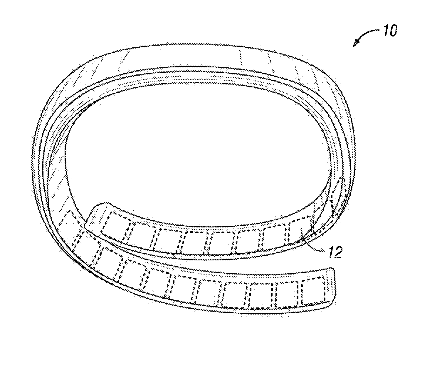
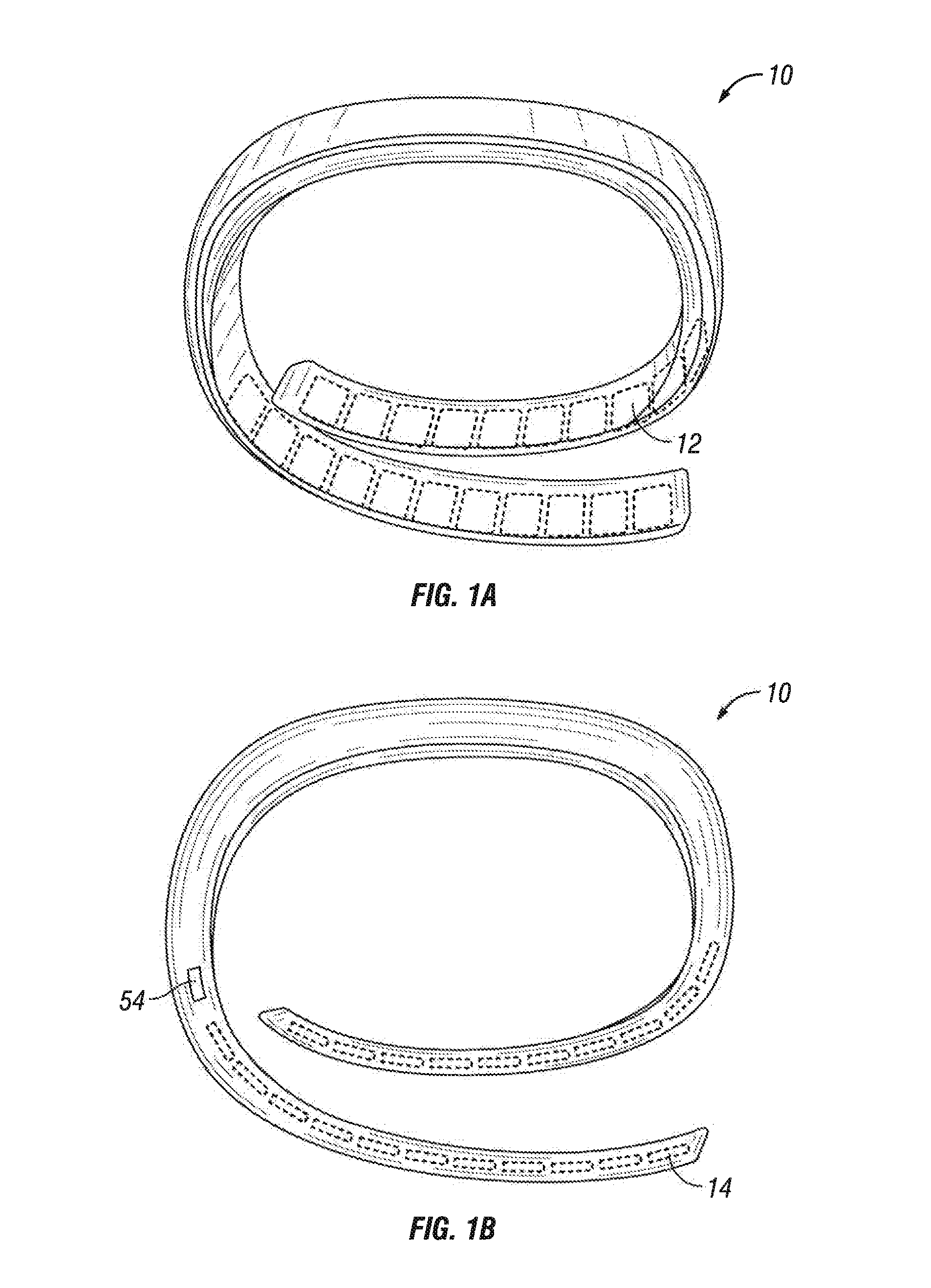
  • Telemetry system with tracking receiver devices
  • Telemetry system with tracking receiver devices
  • Telemetry system with tracking receiver devices

Examples


case 3

[0443 is illustrated by operation 816 and 818. In operation 816, the transmitter may be programmed to expect certain receiver monitoring devices 1520 to be in its coupling-mode region during certain time periods. In addition, portable host monitoring devices 1510B may be programmed to expect receiver monitoring devices 1520 to be at certain locations during certain times. For example, a portable host monitoring device 1510B may be programmed to indicate that a PDA should be in the office during working hours and at home during non-working hours. Thus, a user may pre-set a handbag (e.g., host monitoring device 1510B) capable of charging portable monitoring devices, to expect a certain set of receiver monitoring devices 1520 to be placed within the handbag prior to the bag leaving the house.

[0444]As non-limiting examples, this time and position information that may be programmed into host monitoring devices may be used to allow a host monitoring device to warn if certain receiver moni...


PUM


Abstract

A wireless power transmission system includes, a transmit antenna which in operation produces a wireless field, an amplifier coupled to the transmit antenna, a load sensing circuit coupled to the amplifier and a controller coupled to the load sensing circuit. A monitoring device has one or more sensors and a unique user ID. The one or more sensors acquire user information selected from of at least one of, a user's activities, behaviors and habit information. The monitoring device includes an ID circuitry. A communication interface receives information about the unique user ID when the load sensing circuit indicates the monitoring device is within the wireless field. The indication is created using at least a change in power consumption.

Description

CROSS-REFERENCE TO RELATED APPLICATIONS[0001]This application is a continuation in part of U.S. Ser. No. 13 / 923,909, U.S. Ser. No. 13 / 923,637, U.S. Ser. No. 13 / 923,614, U.S. Ser. No. 13 / 923,809, U.S. Ser. No. 13 / 923,750, U.S. Ser. No. 13 / 923,583, U.S. Ser. No. 13 / 923,560, U.S. Ser. No. 13 / 923,543, and U.S. Ser. No. 13 / 923,937, all filed Jun. 21, 2013 and all of which claim the benefit of U.S. 61 / 772,265, U.S. 61 / 812,083 and 61 / 823,502. All of the above-identified applications are fully incorporated herein by reference.BACKGROUND OF THE INVENTION[0002]1. Field of the Invention[0003]The present invention relates generally to wireless charging, and more particularly to devices, systems, and methods related to tracking receiver monitoring devices that may be located in wireless power systems.[0004]2. Description of the Related Art[0005]Telemetry systems can be implemented to acquire and transmit data from a remote source. Some telemetry systems provide information about a user's activit...

Claims


Application Information

Patent Timeline
IPC IPC(8): G08C17/02H04W4/21H04W4/70H04W4/80
CPCG08C17/02A61B2560/0214A61B2562/08A61B5/6831A61B5/0022A61B5/0205A61B5/1118H04L67/125H04L67/12A61B5/002A61B5/02055A61B5/681A61B5/7275G16H40/67Y04S40/18H04W4/70H04W4/21H04W4/80H02J50/10H02J50/60H02J50/80H02J7/00034H02J50/90H02J50/12H04L67/535H02J2310/23
Inventor PROUD, JAMES
Owner FITBIT INC
Learn More