
Section bar for a heater and fluid flow heater, in particular for coffee machines

a technology for heaters and fluid flow, which is applied in the direction of heating elements, immersion heating arrangements, resistors, etc., can solve the problems of complex machining of the end of the fluid circulation duct, the inability to perform prior brazing procedures, and the disadvantage of complicating the machining of the first phase of the machining

Active Publication Date: 2014-08-21
I R C A S P A IND RESISTENZE CORAZZATE E AFFINI
View PDF0 Cites 5 Cited by
  • Summary
  • Abstract
  • Description
  • Claims
  • Application Information

AI Technical Summary

Benefits of technology

The present invention relates to a section bar for a fluid flow heater, which aims to improve construction simplicity and versatility. The invention also provides a simplified manufacturing method of the fluid flow heater that reduces machining requirements. The section bar has an encased resistor integrated in a duct, which simplifies the machining process of the duct. After the duct is inserted, bending of a lug takes place to simplify the brazing operation. Overall, the invention simplifies the production of fluid flow heaters for coffee machines.

Problems solved by technology

For this reason the brazing procedure cannot be performed prior to the bending / winding of the resistor since it would be deteriorated by the subsequent bending / winding of the resistor.
Said solution presents the disadvantage of having to subject the heater to costly cutting and turning operations at the ends since the ends of the fluid circulation ducts must emerge with respect to the terminals of the resistor and must be especially shaped / machined to allow suitable connections to be fitted to the hydraulic circuit of the domestic appliance or coffee machine.
Thus, although this solution eliminates or reduces brazing of the resistor, it presents the disadvantage of complicating machining on the ends of the fluid circulation duct.

Method used


Image

  • Section bar for a heater and fluid flow heater, in particular for coffee machines
  • Section bar for a heater and fluid flow heater, in particular for coffee machines
  • Section bar for a heater and fluid flow heater, in particular for coffee machines

Examples


Embodiment Construction

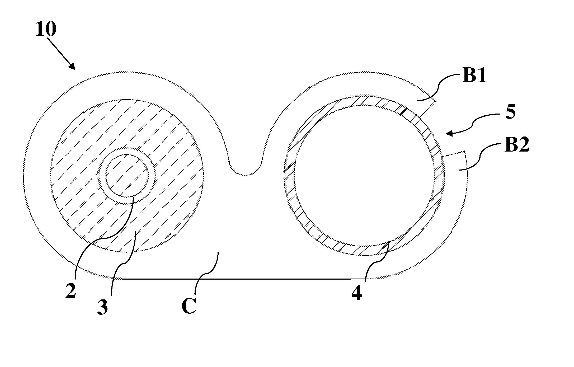
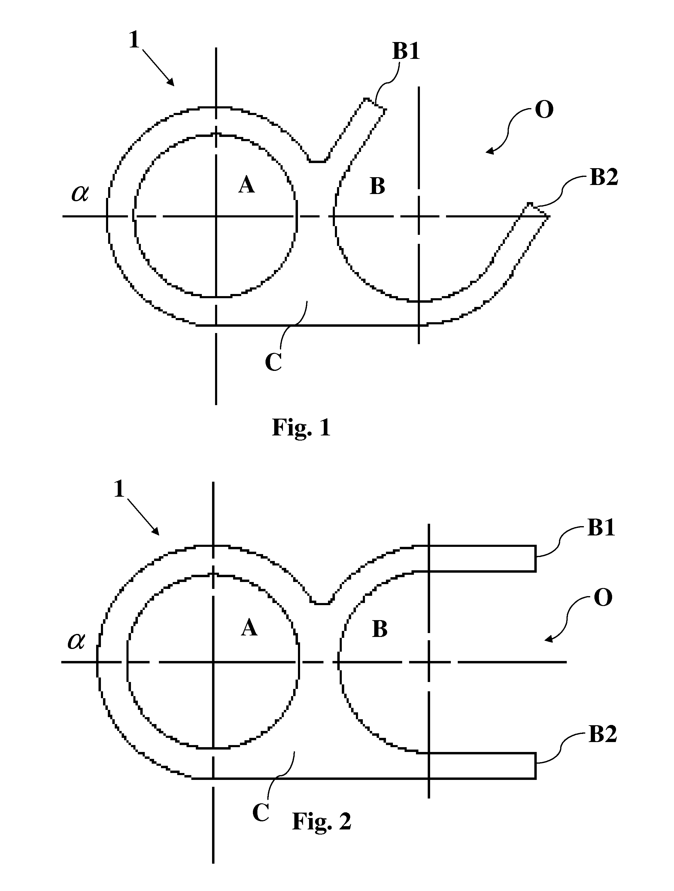
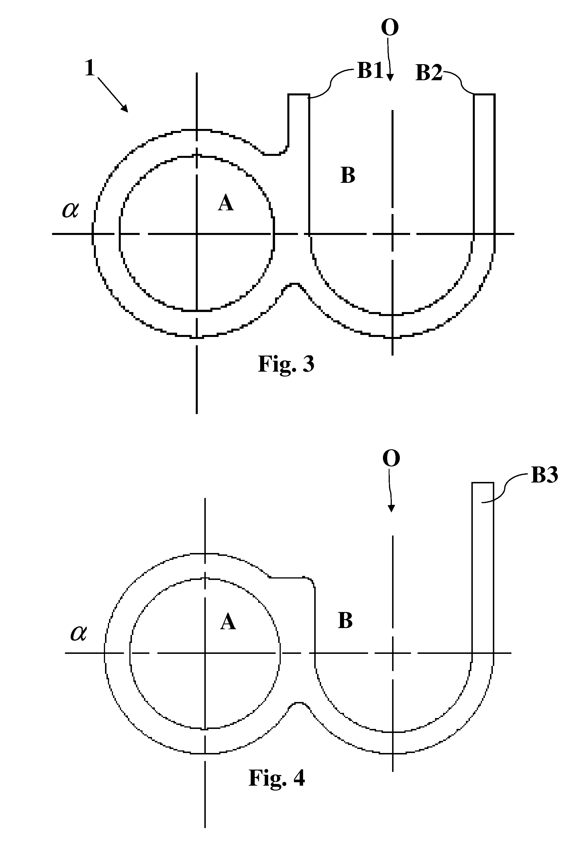
[0025]The drawings represent a cross section representative of the section bar 1, object of the present invention. Said section bar can be obtained for example by extrusion, taking on a longitudinal shape perpendicular to the drawings sheet. According to the cross sections of the drawings, section bar 1 comprises a closed cavity A, that is only accessible at the opposite ends of the section bar, and a second cavity B, that is open along the longitudinal development of the section bar. This second cavity B will also be referred to hereunder as longitudinal cavity.

[0026]In other words, said open cavity is presented as a rectilinear groove that can be accessed and filled with brazing material at any point of the longitudinal development of the section bar.

[0027]The two cavities are integral to form a single body, i.e. enbloc.

[0028]The first cavity A is intended to define an encased resistor, i.e. intended to provide housing[0029]for a resistance wire 2, for example spiral wound,[0030]f...


PUM

PropertyMeasurementUnit
thicknessaaaaaaaaaa
shapeaaaaaaaaaa
thermalaaaaaaaaaa

Abstract

The section bar (1) for a fluid flow heater for coffee machines has a longitudinal development with two opposing ends and a first tubular cavity (A), that is accessible at the opposing ends of the section bar (1), and a second cavity (B) having an opening (O) that extends along the longitudinal development of the section bar (1). A heater (10) having an encased resistor (2, 3) integrated in the first cavity (A) of the section bar (1) and a tubular fluid circulation conduit (4) inserted into the second cavity (B) of the section bar (1) and fixed by means of bending at least one lug (B1, B2, B3) around the tubular fluid circulation conduit (4), so that the opposing ends of the tubular fluid circulation conduit (4) emerge with respect to the opposing ends of the section bar (1).

Description

FIELD OF THE INVENTION[0001]The present invention relates to a section bar for a heater and a fluid flow heater, in particular for coffee machines, and to a related manufacturing method.BACKGROUND OF THE INVENTION[0002]The heating of water in coffee machines is achieved by means of encased resistors, wherein the resistance wire is generally spiral-wound inside a casing. Furthermore, in flow heaters the encased resistor is also typically associated to a tubular duct in which water circulates, so that the respective axes of longitudinal development are parallel to each other.[0003]The duct and the encased resistor thus associated can be arranged, for example spiral-wound, inside a coffee machine to limit the dimensions thereof and so that a tubular duct has the resistor placed side by side on two opposite sides, thus improving the heat exchange.[0004]It is also requested that the heater take on extreme forms in terms of bending angles so that it may adapt to the shape of the domestic ...

Claims


Application Information

Patent Timeline
Patent Type & Authority Applications(United States)
IPC IPC(8): A47J31/54H01C17/02H01C17/04F24H1/10
CPCA47J31/542H01C17/04H01C17/02F24H1/102H05B3/48Y10T29/49083Y10T29/49096
Inventor CAPRARO, DUILIOFOLTRAN, VANIAZOPPAS, FEDERICO
Owner I R C A S P A IND RESISTENZE CORAZZATE E AFFINI
Learn More