
Heave plates that produce large rates of change in tether tension without going slack, and associated systems and methods

a technology of tether tension and tether plate, which is applied in the field of tether plate, can solve the problems of sudden increase in tension force, damage to pto, and pto can be sensitive to slack in the tether,

Inactive Publication Date: 2014-08-21
OSCILLA POWER +1
View PDF20 Cites 15 Cited by
  • Summary
  • Abstract
  • Description
  • Claims
  • Application Information

AI Technical Summary

Benefits of technology

The patent text describes a system for generating energy from water waves using a buoy and a tether. The tether is connected to a submerged electricity-generating device via a tether. The system includes a heave plate that keeps the tether under tension, but can experience slack in the tether and the PTOs (power take-off units) connected to it. To address this problem, the heave plate can include perforations that reduce the drag force when the heave plate moves down, but this also reduces the tension in the tethers and PTOs. The technical effect of this invention is to minimize damage to the PTOs and maximize energy production by optimizing the tension force in the tether and PTOs.

Problems solved by technology

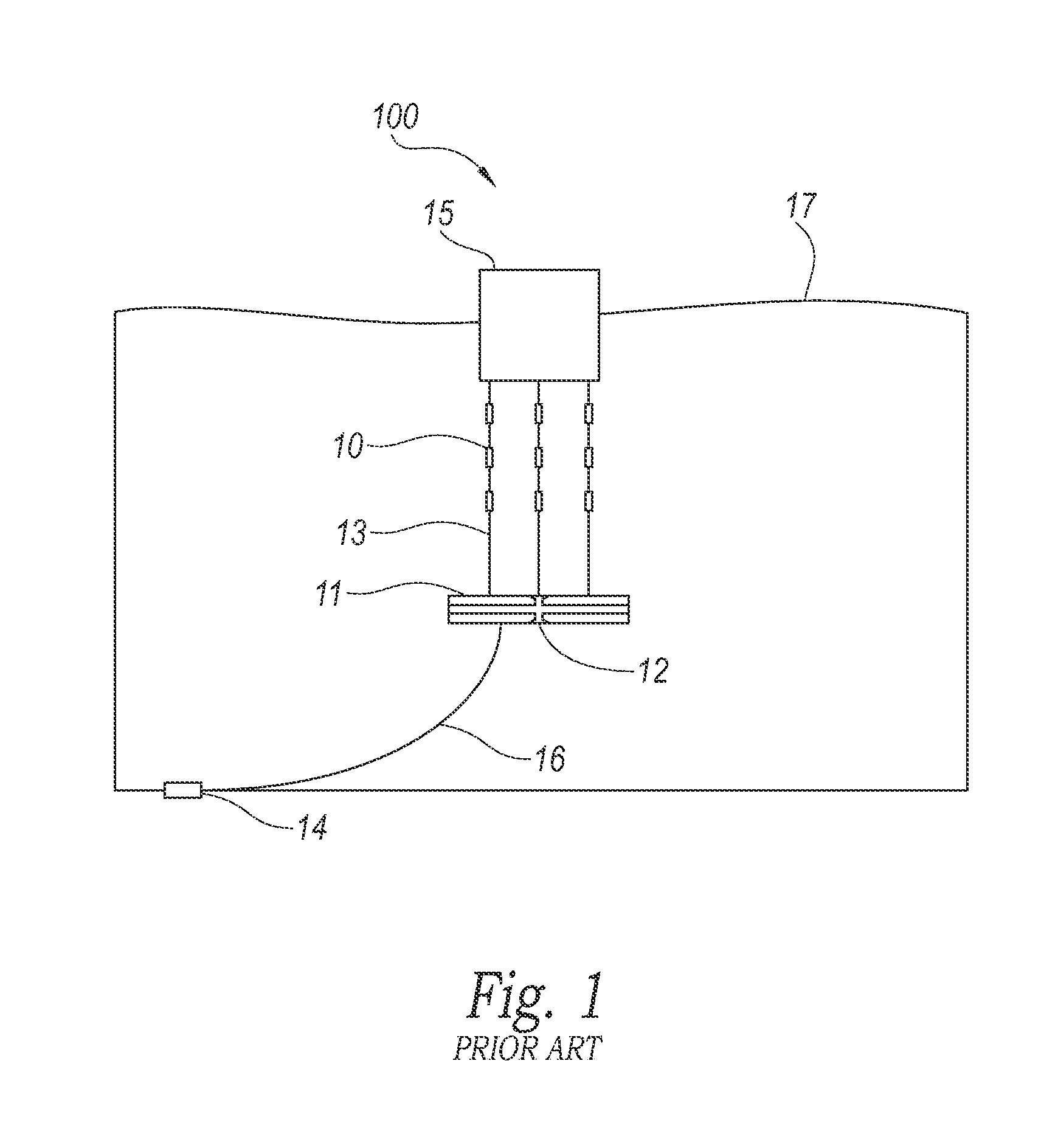
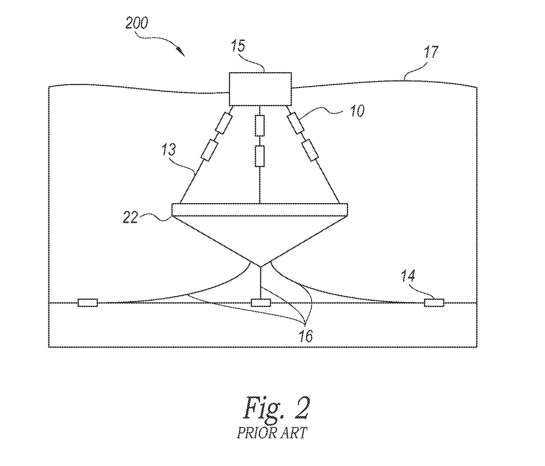
However, the PTOs can be sensitive to slack in the tether.
For example, the PTO can be damaged by a loss of the tension force (corresponding to the slack of the tether), followed by a sudden increase in the tension force (corresponding to the buoy-induced tension in the tether).
As explained above, loss of tension in the PTO followed by sudden tensioning may damage the PTOs.
A reduction in the tension of the PTOs is undesirable because, in general, the PTOs produce more energy when the tension force is higher.

Method used


Image

  • Heave plates that produce large rates of change in tether tension without going slack, and associated systems and methods
  • Heave plates that produce large rates of change in tether tension without going slack, and associated systems and methods
  • Heave plates that produce large rates of change in tether tension without going slack, and associated systems and methods

Examples


Embodiment Construction

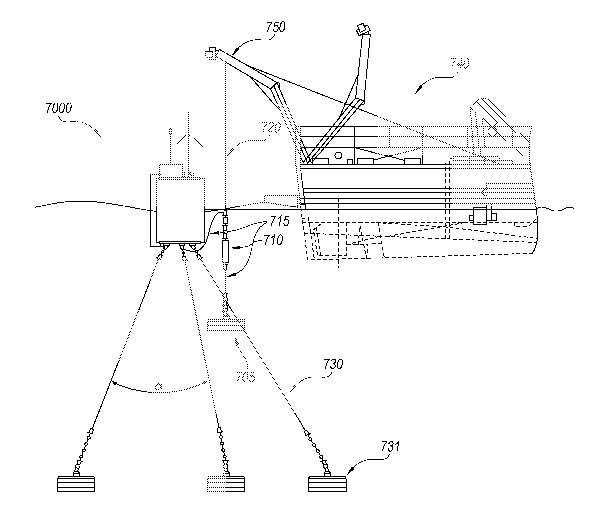
[0015]The present technology relates to systems and methods for generating electrical energy from water waves. In some embodiments, a surface-based buoy can be connected to the magnetostrictive elements (e.g., power take-off units or PTOs) that produce different output voltage as tension changes in the PTOs. Since the PTOs can be sensitive to zero tension followed by a sudden increase in tension, it is preferred to keep the PTOs tensioned at all times. Therefore, in some embodiments of the present technology, a heave plate can be attached to a tether that is connected to the PTOs. The heave plate can be inertia dominated to provide tension in the tether and the PTOs for a range of expected wave and / or tide events. According to embodiments of the present technology, the inertia dominated heave plate is designed to sink faster than the buoy falls into the trough of the wave, therefore keeping the tether tensioned at all times. For example, design parameters of the heave plate (e.g., m...


PUM

PropertyMeasurementUnit
weightaaaaaaaaaa
diameteraaaaaaaaaa
tensionaaaaaaaaaa

Abstract

Apparatuses and associated methods for converting wave energy into electrical energy are disclosed herein. In some embodiments, a surface-based buoy can be connected to a magnetostrictive element that changes its output voltage when subjected to the in tension. To keep the heave plate under tension, a tether with a heave plate can be attached to the magnetostrictive element. Since the magnetostrictive element can be sensitive to zero tension (e.g., a slack in the tether) followed by a sudden increase in the tension, in at least some embodiments it is preferred to keep the magnetostrictive element tensioned at all times. In some embodiments of the present technology, an inertia-dominated heave plate may be designed to sink faster than the buoy falls in the trough of the wave, therefore keeping the tether tensioned at all times. For example, the design (e.g., mass, diameter, height) of the heave plate can be such that the static force of gravity S exceeds a sum of the drag D and inertia I under expected wave conditions.

Description

CROSS-REFERENCE TO RELATED APPLICATIONS[0001]This application claims the benefit of U.S. Provisional Application No. 61 / 767,689, filed Feb. 21, 2013.TECHNICAL FIELD[0002]The present technology is generally related to systems that generate electrical energy from water waves. The systems typically include a buoy connected to a submerged electricity-generating device via a tether. In particular, several embodiments of the present technology are directed to heave plates that keep the tether under tension for a range of wave and / or tide events.BACKGROUND[0003]Water wave energy is a known source of renewable energy. With some conventional technologies, a relatively light buoy is placed in a water body such that the buoy bobs up with a wave crest and down with a wave trough. This up and down motion of the buoy can be harnessed as renewable energy. For example, the buoy can be tethered to a device, e.g., a mechanical spring or a gas compressor, capable of storing the motion of the buoy as p...

Claims


Application Information

Patent Timeline
Patent Type & Authority Applications(United States)
IPC IPC(8): F03B13/16F03B13/10
CPCF03B13/10F03B13/16F03B13/20B63B2209/14F05B2280/5008Y02E10/30A61K31/337A61K31/451A61K31/473A61K45/06
Inventor THOMSON, JAMES M.TALBERT, JOSEPH L.DEKLERK, ALEXRUSCH, CURTISMURPHREE, ZACHARY
Owner OSCILLA POWER
Learn More