
Hybrid power and propulsion system

a hybrid power and propulsion system technology, applied in marine propulsion, vessel construction, transportation and packaging, etc., can solve the problems of limited efficiency of the propulsion system with azimuthing drive, difficult to provide efficient gearing that enables full use of the driving engine and the propulsor throughout both optimum speed and loading ranges

Active Publication Date: 2014-07-03
GE GLOBAL SOURCING LLC
View PDF4 Cites 30 Cited by
  • Summary
  • Abstract
  • Description
  • Claims
  • Application Information

AI Technical Summary

Benefits of technology

The patent describes an azimuthing drive system for marine vessels that allows for the sharing or dividing of propulsion loads between an engine and an electric motor. The system includes a propulsion pod that rotates about a horizontal axis and is driven by a vertical shaft. The system also includes a gearbox connected to the shaft, an engine connected to the gearbox, and an electric motor connected to the gearbox. The electric motor can be connected to the shaft in three different configurations, allowing for the sharing or division of propulsion loads. The method of propelling a marine vessel involves operating both the engine and the electric motor and transferring power from the gearbox to the propulsor. The technical effect of this system is improved efficiency and flexibility in the propulsion of marine vessels.

Problems solved by technology

In operation, efficiency of the propulsion system with azimuthing drive is limited by the fuel consumption profile of the driving engine (prime mover).
Intervening gearing can aid in achieving a desirable combination of engine speed and propulsor speed, however, it is difficult to provide efficient gearing that enables full use of the driving engine and of the propulsor throughout both optimum speed and loading ranges.

Method used


Image

  • Hybrid power and propulsion system
  • Hybrid power and propulsion system
  • Hybrid power and propulsion system

Examples


first embodiment

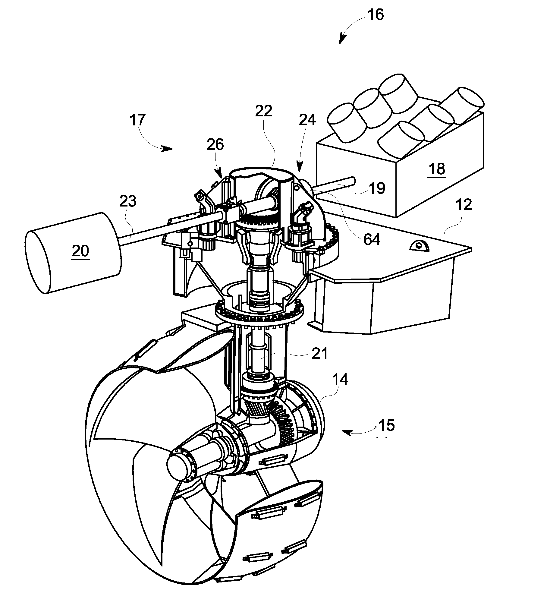
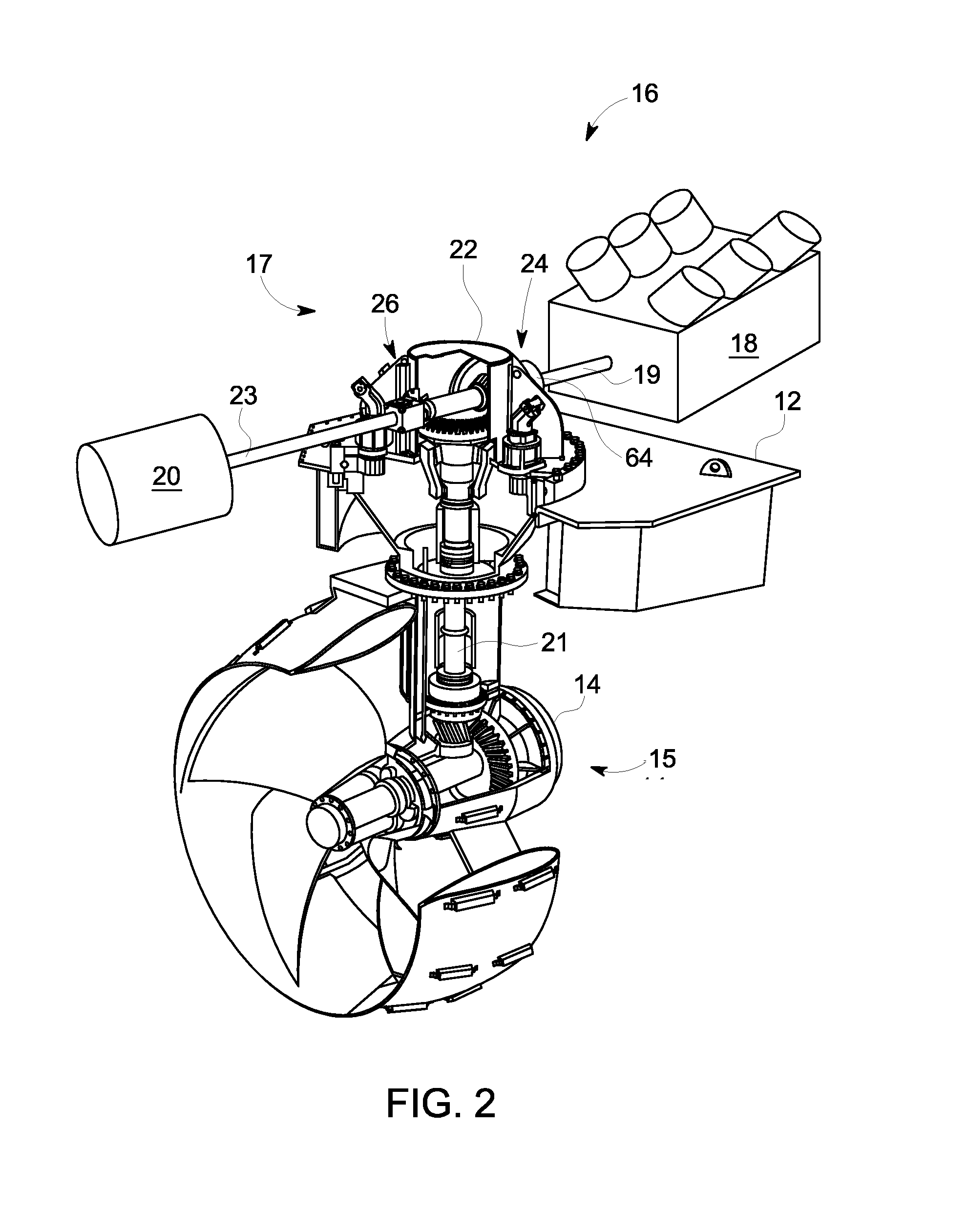
[0030]Referring to FIG. 2, in the invention, e.g., a “T arrangement”16, each azimuthing propulsion unit 14 is configured such that its propulsor 15 can be driven from a hybrid power system 17 via a first (e.g., vertical) shaft 21. The hybrid power system 17 includes a propulsion engine 18 (e.g., a diesel propulsion engine) and an electric motor 20, each of which drive the first shaft 21 via a common gearbox 22. The first shaft 21 defines the axis about which the propulsor 15 can be swiveled. The arrangement 16 is generally referred to as a “T” arrangement because the shaft 19 of the engine 18 and the shaft 23 of the electric motor 20 form a “T” shape with the first shaft 21.

[0031]In embodiments, the engine 18 has a designated running speed and load range for optimum fuel efficiency. Typically, the optimum load range is 40-90% of maximum rated power. The electric motor 20 may operate on any of fixed or variable voltage DC, or fixed or variable voltage and frequency AC. The electric m...

second embodiment

[0034]Referring to FIG. 3, in the invention, e.g., a vertical motor arrangement 28, the engine 18 (e.g., diesel propulsion engine) and the electric motor 20 are connected with the first shaft 21 via a common gearbox 29. The gearbox 29 includes the first bevel gear set 24 as well as a ring gear set 30 for connecting the electric motor. The ring gear set 30 is used because in the vertical motor arrangement 28, the electric motor 20 is provided with its shaft coaxial, coplanar, or in a parallel plane with the first shaft 21. In other words the electric motor 20 is vertically mounted. This configuration conserves horizontal space. Additionally, use of the ring gear set 30 enables a higher speed reduction ratio for the electric motor 20.

[0035]FIG. 4 shows a third embodiment of the invention, e.g., an “L arrangement”32, in which the electric motor 20 directly drives the first shaft 21. Thus, the electric motor 20 can be operated either as a motor (assisting the engine 18 in driving the fi...


PUM


Abstract

An azimuthing drive system is provided for marine vessels. The azimuthing drive system includes a propulsion pod that houses a propulsor, which is configured to rotate about a first axis and to be driven by a first shaft generally orthogonal to the first axis. The propulsion pod is configured to swivel about the first shaft. The drive system also includes a gearbox connected to drive the first shaft, a diesel engine connected to drive the gearbox via a second shaft, and an electric motor connected to drive the first shaft via the gearbox or directly, whereby propulsion loads are shared between the diesel engine and the electric motor.

Description

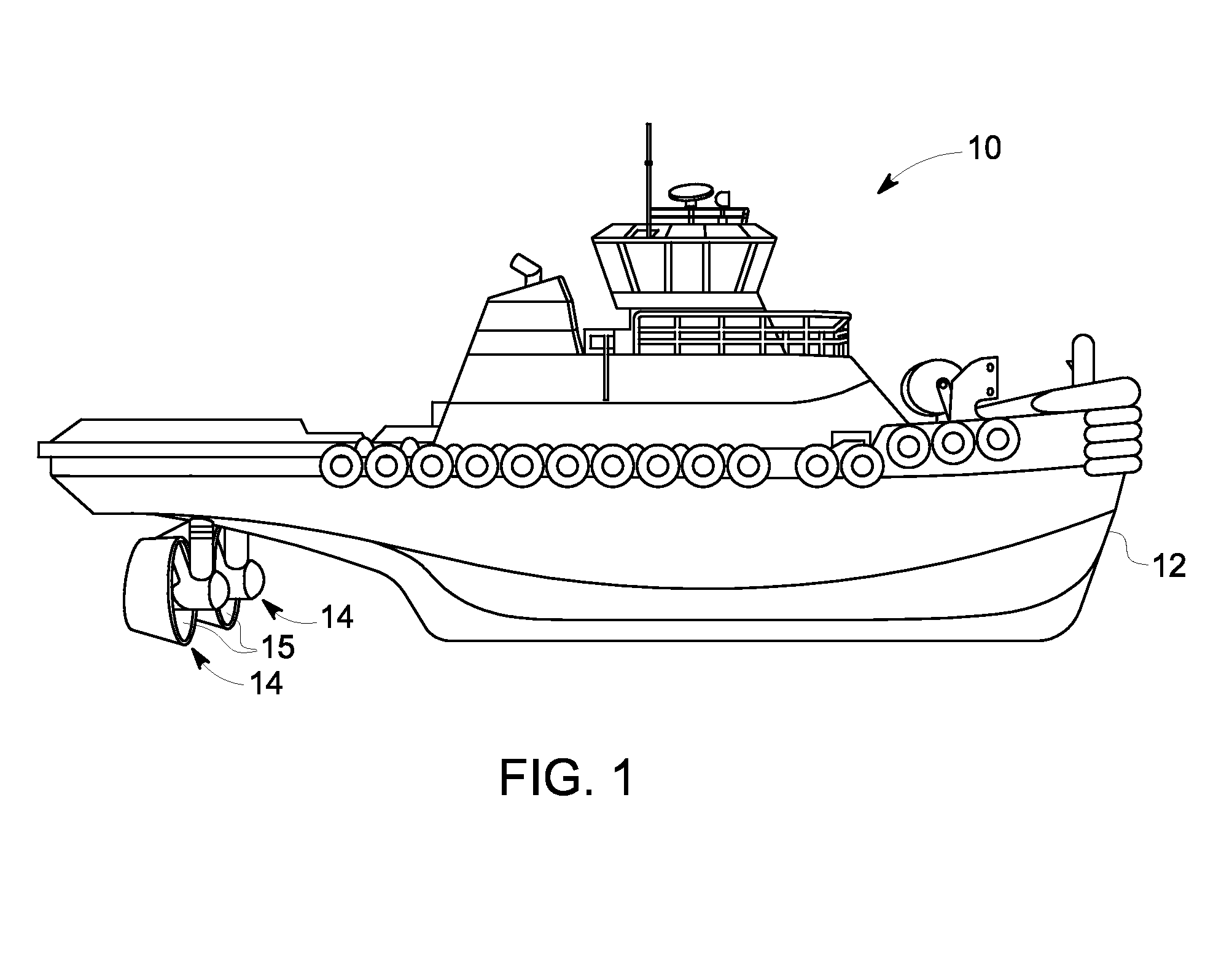
BACKGROUND[0001]1. Technical Field[0002]Embodiments of the invention relate generally to marine propulsion. Particular embodiments relate to azimuthing drives for marine propulsion.[0003]2. Discussion of Art[0004]Marine propulsion can be accomplished by various means. Most commonly, a marine vessel is driven forward by a shaft-mounted propulsor external to the vessel, such as an open propeller or a shrouded screw. Also known are water jet propulsors, which are essentially screws shrouded by the marine vessel itself. Such means for propulsion can be configured as azimuthing drives, which include propulsors that can be swiveled about axes perpendicular to the thrust axis of the drive, thereby redirecting the thrust force within an azimuthal plane.[0005]Conventionally, an azimuthing drive has its propulsor driven from a vertical shaft, which in turn is driven by a vertically- or horizontally-arranged engine, e.g., a diesel engine. For example, a horizontally-arranged engine will have i...

Claims


Application Information

Patent Timeline
IPC IPC(8): B63H21/20
CPCY10S903/902B63H21/20B63B35/66B63H2005/1256B63H2021/205B63H2021/216Y02T70/5236B63H21/22
Inventor GEMIN, PAUL ROBERTWIEGMAN, HERMAN LUCAS NORBERT
Owner GE GLOBAL SOURCING LLC
Learn More