
Accumulated type thermoelectric generator for vehicle

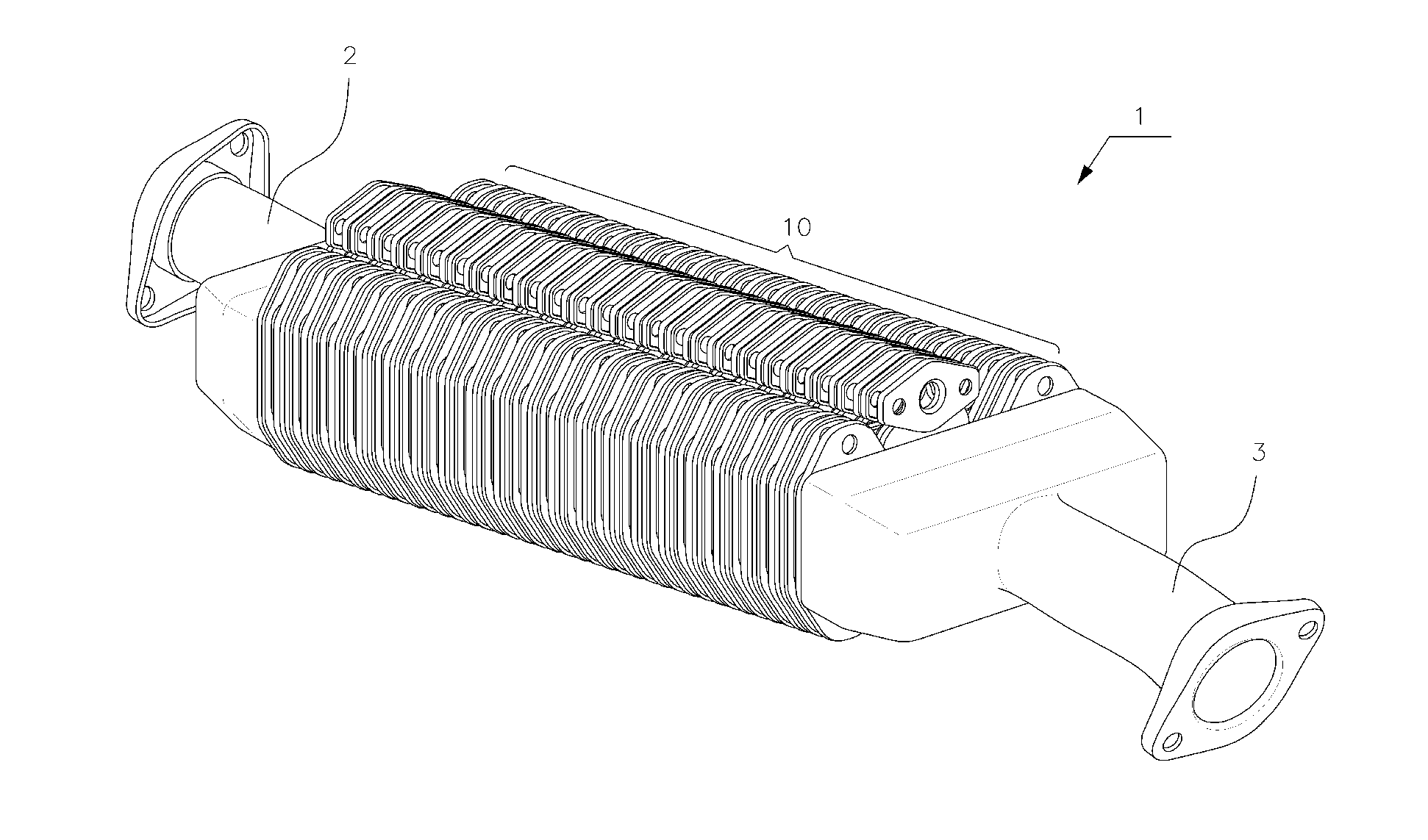
a technology of thermoelectric generator and accumulated type, which is applied in the direction of thermoelectric devices, machines/engines, mechanical instruments, etc., can solve the problems of increasing fuel consumption, reducing the application area of thermoelectric elements, and reducing the temperature difference between the high temperature end and the low temperature end, so as to improve the amount of thermoelectric power generation, increase the application area of thermoelectric elements, and efficiently configure the path

Active Publication Date: 2014-07-03
HYUNDAI MOTOR CO LTD
View PDF4 Cites 8 Cited by
  • Summary
  • Abstract
  • Description
  • Claims
  • Application Information

AI Technical Summary

Benefits of technology

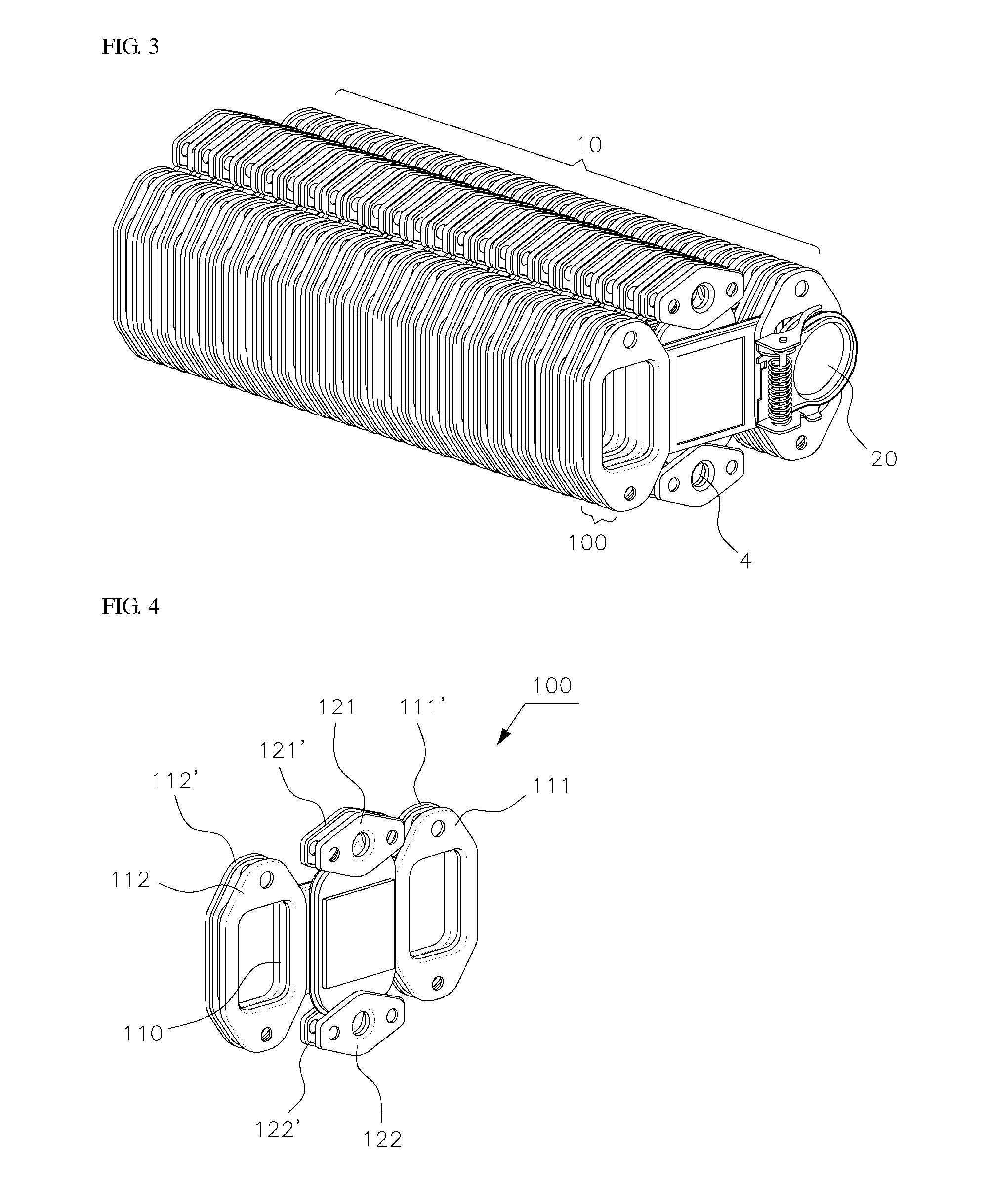
The present invention is a thermoelectric generator for a vehicle that improves power generation efficiency by improving the heat exchange structure. It includes a plurality of accumulated unit modules, each containing thermoelectric elements, which increases the application area and maximizes power generation. The configuration of the thermoelectric generating unit is flexible and can adjust to changes in output amount and layout constraints of the vehicle. The unit modules are easily replaced and maintained, and the components are simplified for mass production with excellent structural strength. Overall, the thermoelectric generator for a vehicle has excellent performance and is suitable for mass production.

Problems solved by technology

Meanwhile, since the efficiency of an engine driving alternating current generator (also called an alternator), which supplies electrical power within a vehicle to charge the battery, is only operating at about 33% efficiency, and the shaft power of the alternator should be increased as electric power consumption of the vehicle is increased, as the loss of the shaft power is increased, fuel consumption becomes increases, and an increase of pollutants are discharged due to the high fuel consumption.
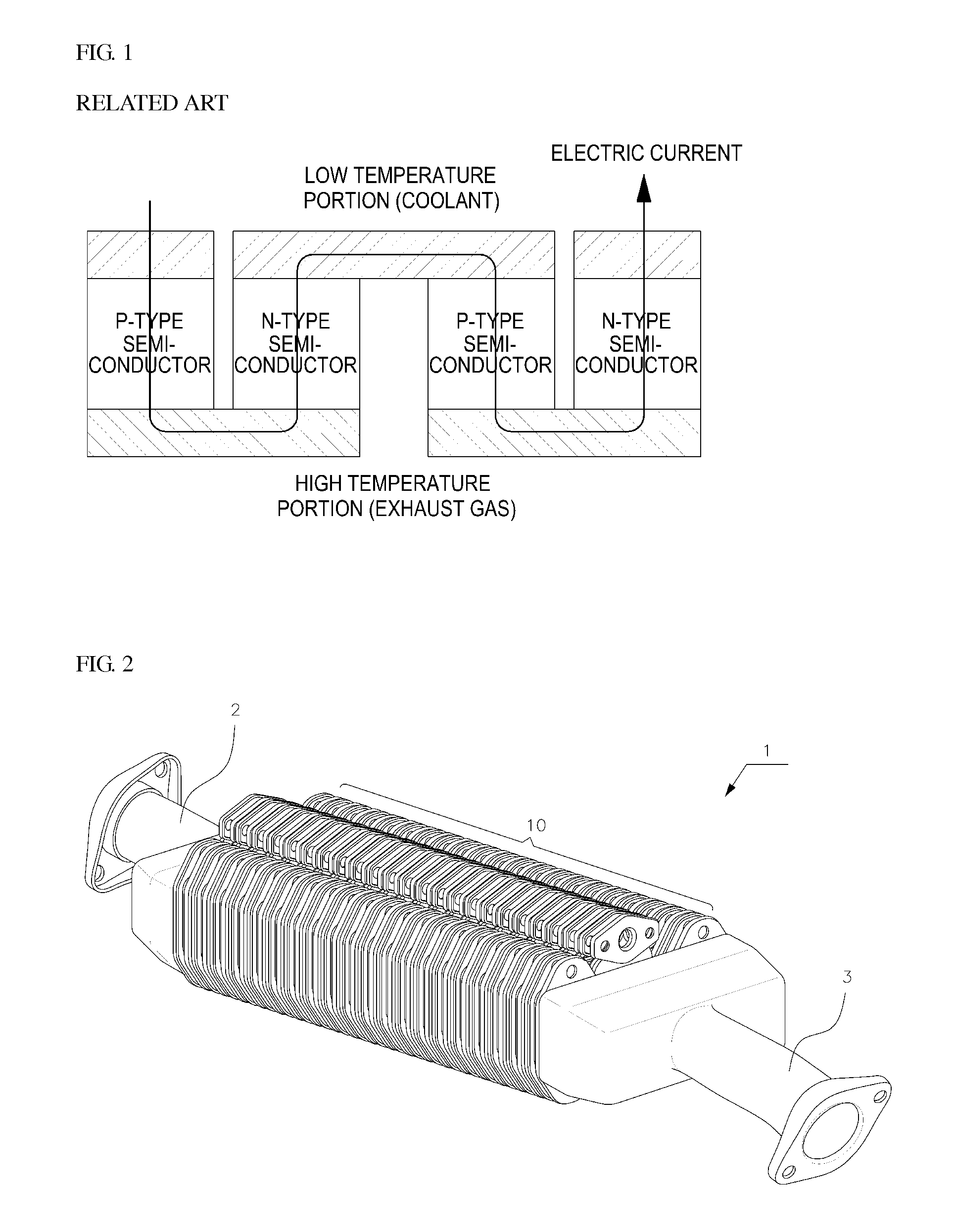
However, it is necessary to maximize a temperature difference between the heating unit and the cooling unit to increase the amount of power generated by the thermoelectric module, but because the structural efficiency of the heating unit and the cooling unit is currently poor in the thermoelectric generator for a vehicle of the related art like the one shown in FIG. 1, the temperature difference between the high temperature end and the low temperature end is smaller than what is desirable.

Method used


Image

  • Accumulated type thermoelectric generator for vehicle
  • Accumulated type thermoelectric generator for vehicle
  • Accumulated type thermoelectric generator for vehicle

Examples


Embodiment Construction

[0028]It is understood that the term “vehicle” or “vehicular” or other similar term as used herein is inclusive of motor vehicles in general such as passenger automobiles including sports utility vehicles (SUV), buses, trucks, various commercial vehicles, watercraft including a variety of boats and ships, aircraft, and the like, and includes hybrid vehicles, electric vehicles, combustion, plug-in hybrid electric vehicles, hydrogen-powered vehicles and other alternative fuel vehicles (e.g. fuels derived from resources other than petroleum).

[0029]Additionally, it is understood that the below modules and units are embodied as hardware that is made up of structural components and should not be interpreted as software for the purposes of this application. Additionally, the terminology used herein is for the purpose of describing particular embodiments only and is not intended to be limiting of the invention. As used herein, the singular forms “a”, “an” and “the” are intended to include t...


PUM


Abstract

In one embodiment, a thermoelectric generator for a vehicle is provided. In particular, a thermoelectric generator is provided that includes a thermoelectric generating unit which is mounted between an exhaust gas inlet pipe through which an exhaust gas flows within and an exhaust gas outlet pipe through which the exhaust gas is discharged. The thermoelectric generating unit also includes a coolant inlet formed on one side thereof and a coolant outlet formed on the other side. More specifically, the thermoelectric generator is formed by assembling a plurality of unit modules which each have thermoelectric elements.

Description

CROSS-REFERENCE TO RELATED APPLICATIONS[0001]This application claims priority under 35 U.S.C. §119 to Korean Patent Application No. 10-2012-0158125, filed on Dec. 31, 2012, in the Korean[0002]Intellectual Property Office, the disclosure of which is incorporated herein by reference in its entirety.BACKGROUND OF THE INVENTION[0003]1. Field of the Invention[0004]The present invention relates to a thermoelectric generator for a vehicle, and more particularly, to a thermoelectric generator for a vehicle including a thermoelectric generating unit which is mounted between an exhaust gas inlet pipe through which an exhaust gas flows in and an exhaust gas outlet pipe through which the exhaust gas is discharged, has a coolant inlet formed on one side and a coolant outlet formed on the other side thereof, and is formed by assembling a plurality of unit modules each having thermoelectric elements.[0005]2. Description of the Related Art[0006]In general, a thermoelectric generator refers to an ap...

Claims


Application Information

Patent Timeline
Patent Type & Authority Applications(United States)
IPC IPC(8): H01L35/32
CPCH01L35/32F01N5/025Y02T10/12H10N10/17H10N10/13F02G5/02F01N5/02
Inventor SEON, JONG-HOAN, HO-CHAN
Owner HYUNDAI MOTOR CO LTD
Learn More