
Systems and methods for applying a residual error image

a residual error and image technology, applied in the field of systems and methods for applying residual error images, can solve the problems of not providing a mechanism to add a residual error image to the canvas of hypertext markup language (html) canvas, and the current compression/decompression process is difficult to implement efficiently in a resource-constrained or browser-based clien

Active Publication Date: 2014-06-26
VMWARE INC
View PDF0 Cites 7 Cited by
  • Summary
  • Abstract
  • Description
  • Claims
  • Application Information

AI Technical Summary

Benefits of technology

The patent describes a system and method for adding a residual error image to an existing HTML canvas using native primates. The system generates a positive and negative residual error image based on the differences between the current image and an updated image. The positive residual error image is added to the current image to create a partially updated image, which is then xored with the inverse image to create the updated image. The negative residual error image is added to the inverse image to create an updated inverse image, which is then xored to revert back to the original image. The technical effect of this patent is the ability to add a residual error image to an existing HTML canvas using native primates, resulting in a more precise and accurate update of the image.

Problems solved by technology

However, current compression / decompression processes are difficult to implement efficiently in a resource-constrained or browser-based client.
For example, with a browser based client executing JavaScript™ (“JavaScript”), current compression / decompression processes are difficult to implement efficiently because JavaScript is too slow to operate on individual pixels at high resolution with high frame rates.
Further, a HyperText Markup Language (HTML) canvas does not provide a mechanism to add a residual error image to the canvas.

Method used


Image

  • Systems and methods for applying a residual error image
  • Systems and methods for applying a residual error image
  • Systems and methods for applying a residual error image

Examples


Embodiment Construction

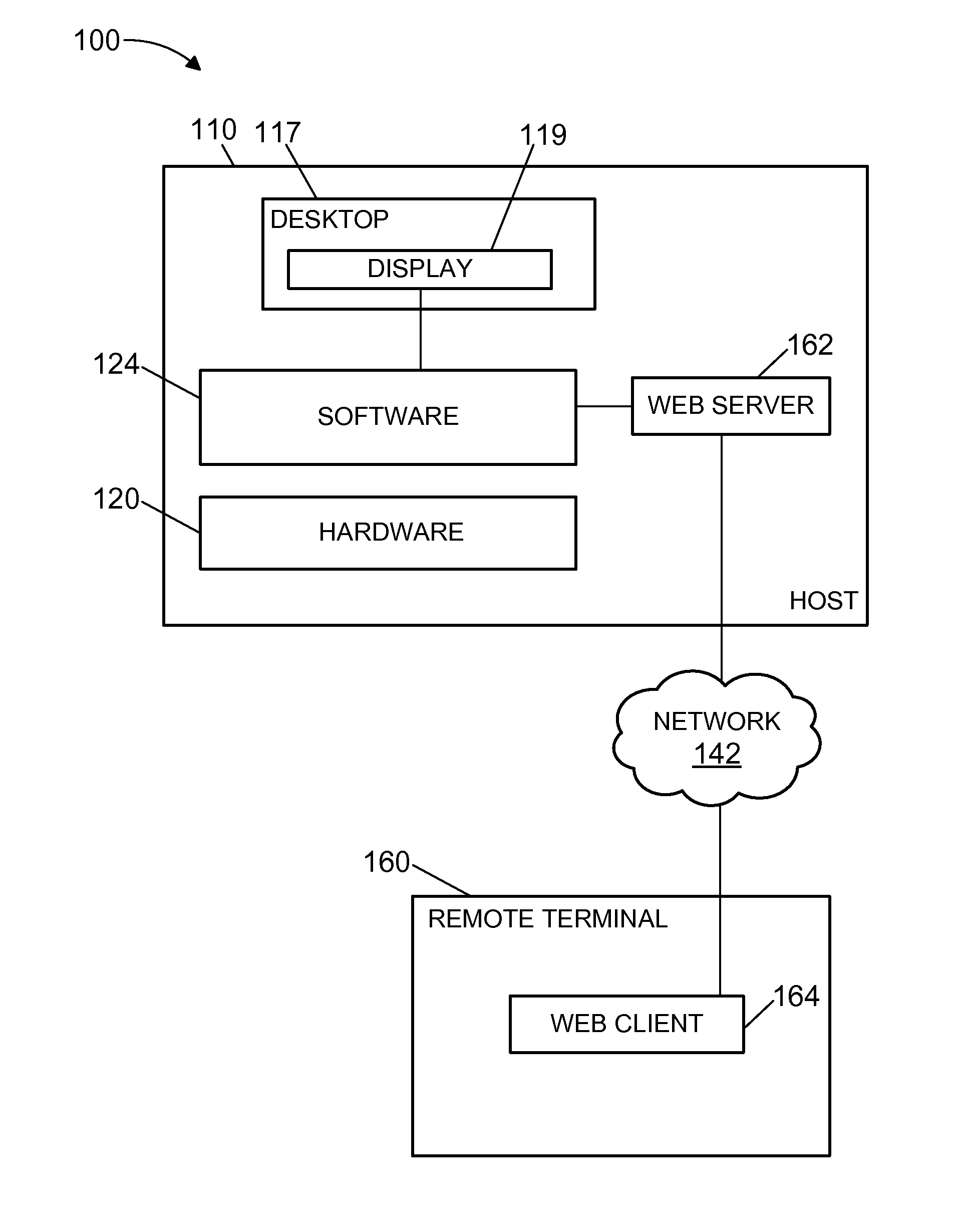
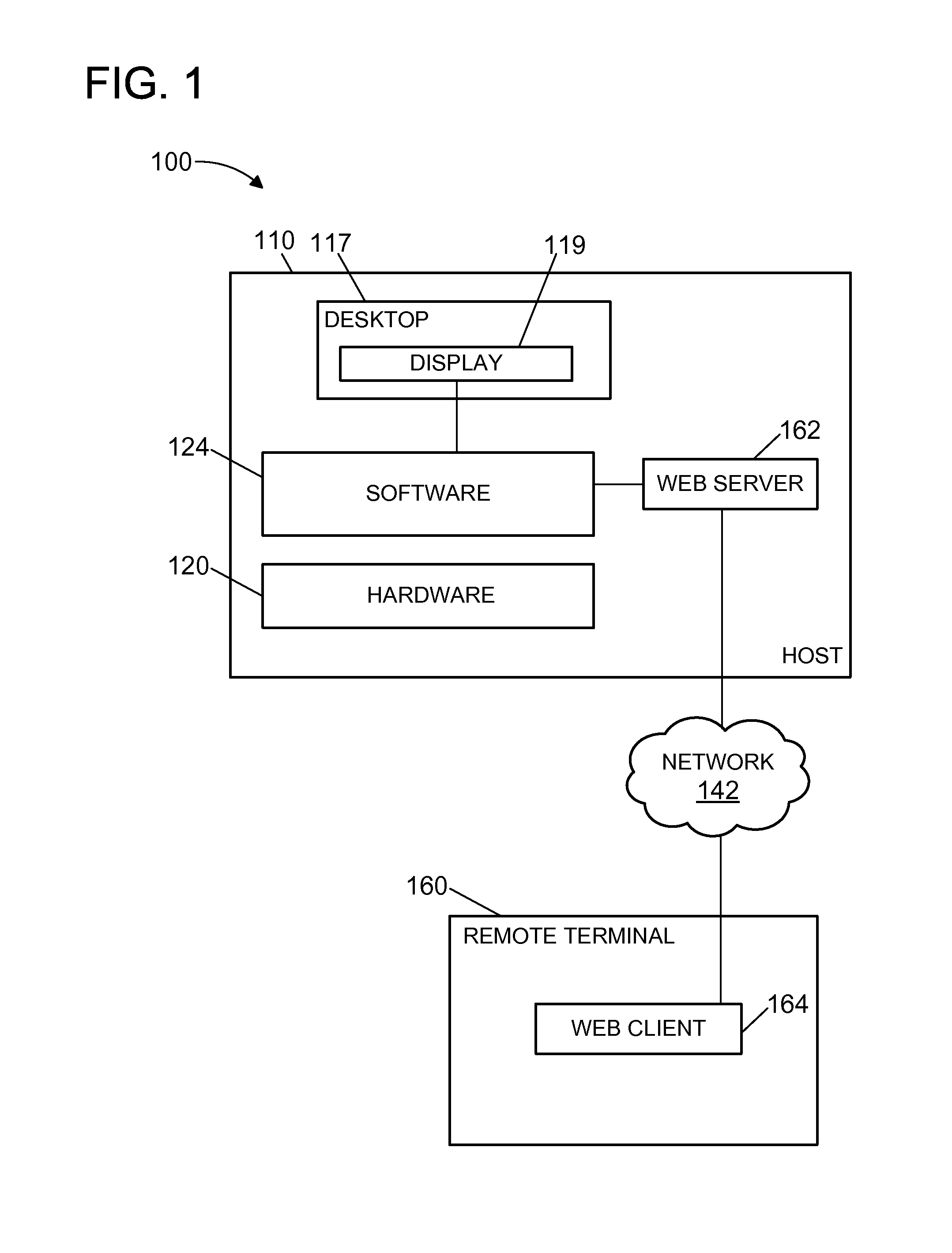
[0007]FIG. 1 shows an exemplary system 100 that includes a physical computer system or host 110. Host 110 includes hardware 120 and software 124 running on the hardware 120 such that various applications may be executing on hardware 120 by way of software 124. Software 124 may be implemented directly in hardware 120, e.g., as a system-on-a-chip, firmware, FPGA, etc. Hardware 120 includes at least one processor (not shown), wherein each processor is an execution unit, or “core,” on a microprocessor chip. Hardware 120 also includes a system memory (not shown), which is a general volatile random access memory (RAM), a network interface (NIC), and other devices.

[0008]In the exemplary embodiment, an end user may connect to, and interact with, host 110 using a remote terminal 160 that is capable of communicating with host 110 via a network 142, which may be the Internet, a LAN, a WAN, or any combination thereof. Remote terminal 160 may be a desktop computer, laptop, mobile device, thin cl...


PUM


Abstract

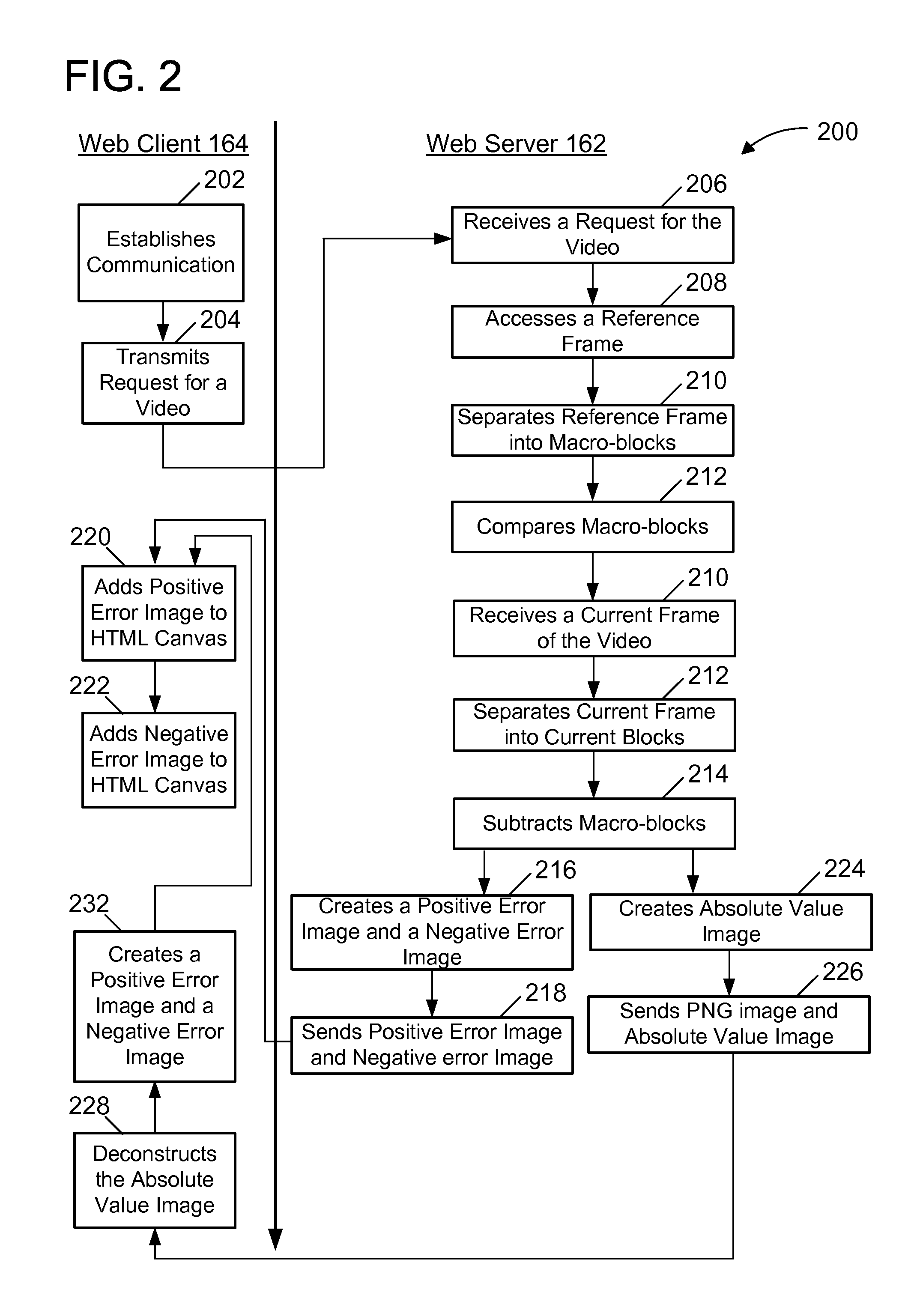
Systems and methods described herein enable a residual error image to be added and rendered in an existing HTML canvas using native primitives. A current image and a residual error image containing pixel value differences between the current image and an updated image are received. A positive residual error image and a negative error image are generated from the residual error image. The positive residual error image is added to the current image to generate a partially updated image, and the partially updated image is xored to generate an inverse image. The negative residual error image is added to the inverse image to generate an updated inverse image, and xoring the inverse image to revert the inverse image to generate the updated image.

Description

BACKGROUND[0001]An important aspect of most methods for compressing sequences of digital video images is motion analysis. In typical motion analysis, a target image in a sequence of images is divided into a plurality of blocks of pixels. A target region that includes at least one pixel block is selected from the target image. The image preceding the target image is analyzed pixel by pixel in order to locate a region of the preceding image that closely matches the target region of the target image. Block matching techniques based on mean-square-error or mean-absolute-error are typically used to locate the region of the preceding image that closely matches the target region of the target image. If no motion has occurred, the preceding and target regions will have the same coordinates within the image frame. If motion has occurred, the preceding region will be offset or translated relative to the target region by an amount that is represented by a displacement vector. This process is t...

Claims


Application Information

Patent Timeline
Patent Type & Authority Applications(United States)
IPC IPC(8): G06F17/22G06F40/143
CPCH04N19/503H04N19/137H04N19/182H04N19/90G06F16/40G06F40/143G06F40/146H04N19/174H04N19/521G06T11/60
Inventor CLARK, JONATHAN
Owner VMWARE INC
Learn More