
Driving unit and battery-assisted bicycle

Active Publication Date: 2014-06-19
YAMAHA MOTOR CO LTD
View PDF6 Cites 13 Cited by
  • Summary
  • Abstract
  • Description
  • Claims
  • Application Information

AI Technical Summary

Benefits of technology

This patent is about a battery-assisted bicycle that has a driving unit that can detect if there is a failure in the torque detector, crank rotation detector, or motor rotation detector. This allows for accurate control of the electric motor and ensures that the bicycle is always functioning properly. The technical effect of this patent is to provide a safer and more reliable battery-assisted bicycle that can always be trusted for use.

Problems solved by technology

In such a structure adapted to detect a torque generated at the crankshaft, if the torque detector that detects a torque has a failure, appropriate assist control based on the rider's pedaling effort cannot be achieved.
As described above, failures in the sensors for use in assist control in a battery-assisted bicycle (such as a torque detector, a crank rotation detector, and a motor rotation detector) cannot be detected with high accuracy using the conventional structure.

Method used


Image

  • Driving unit and battery-assisted bicycle
  • Driving unit and battery-assisted bicycle
  • Driving unit and battery-assisted bicycle

Examples


first preferred embodiment

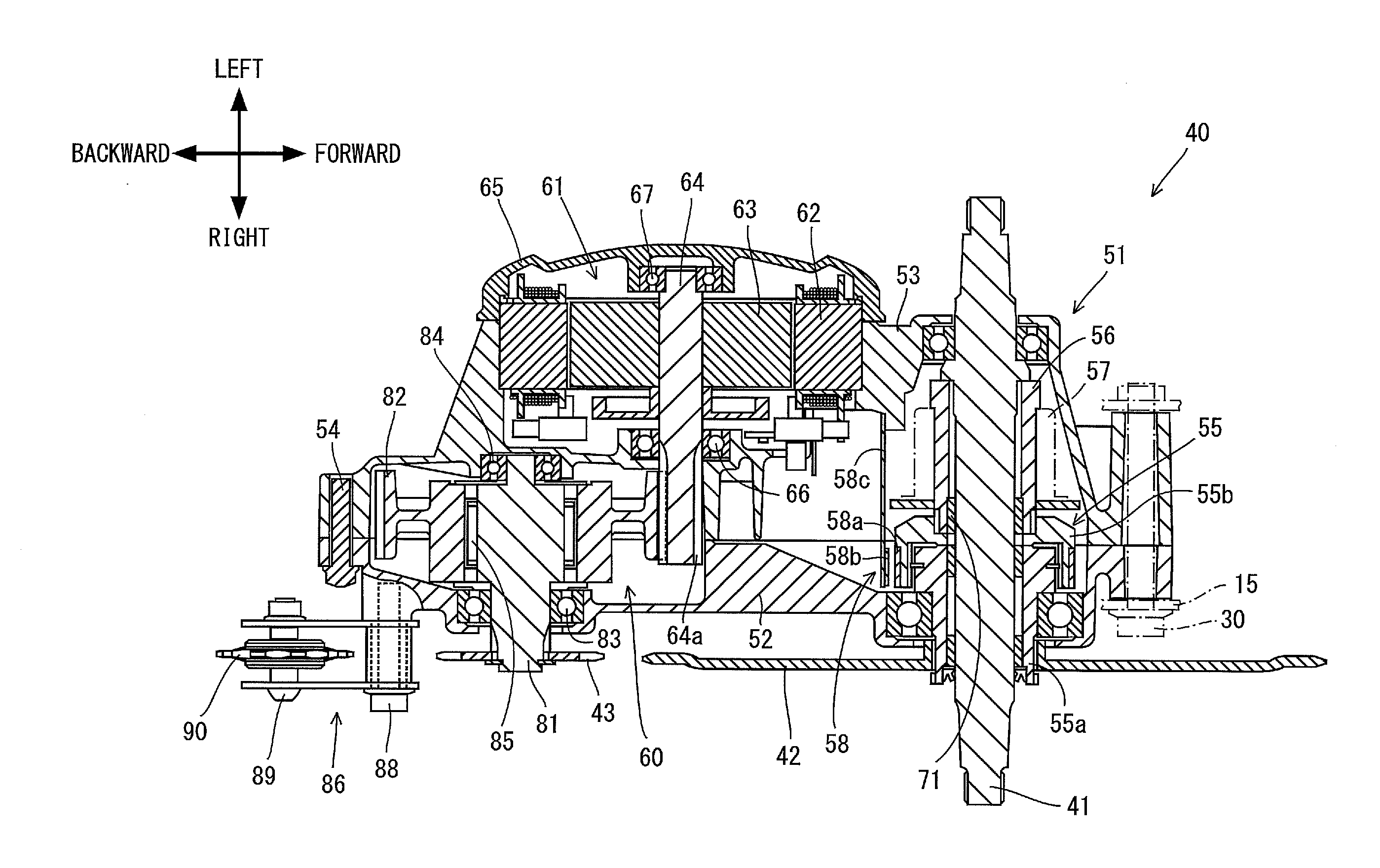
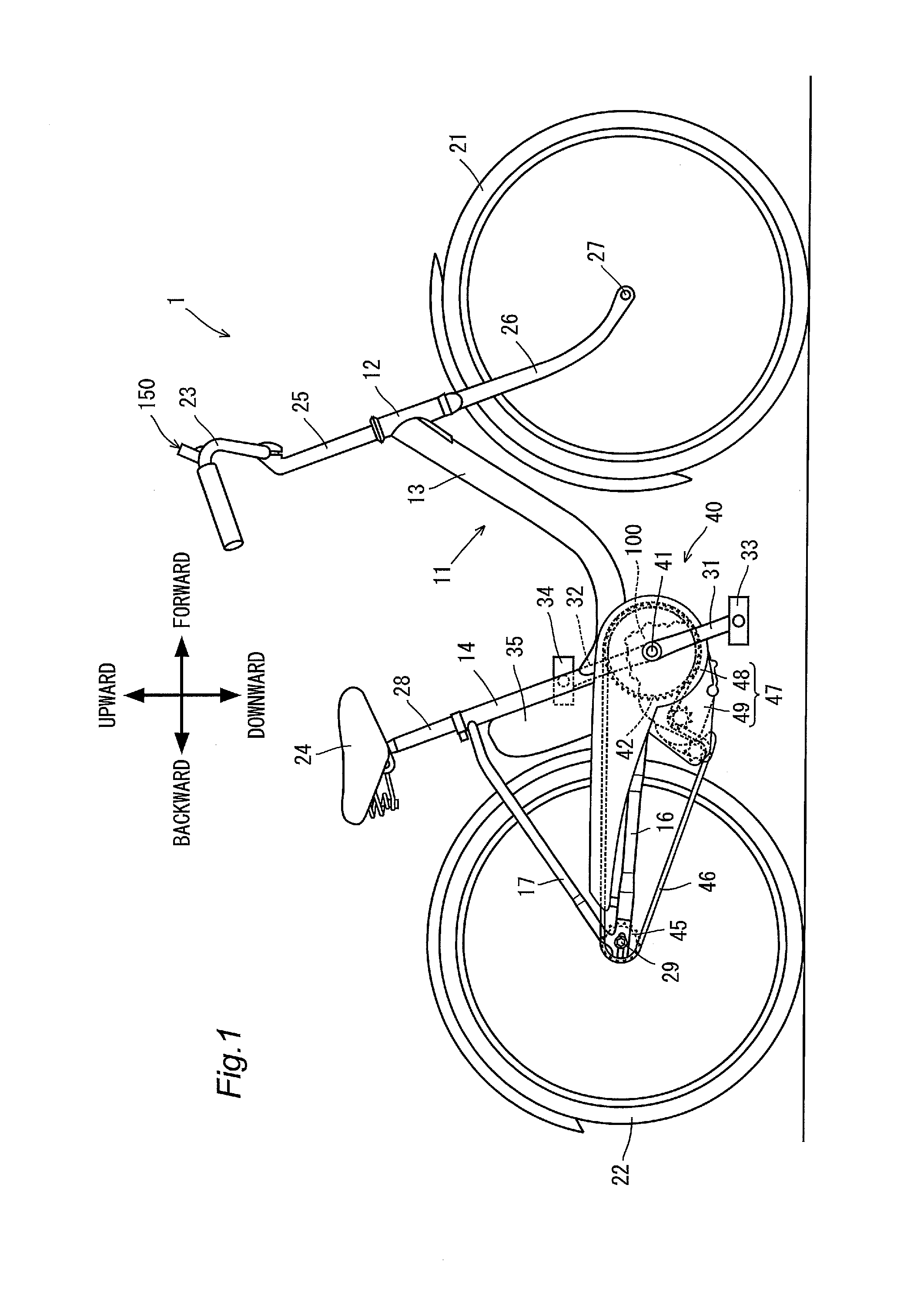
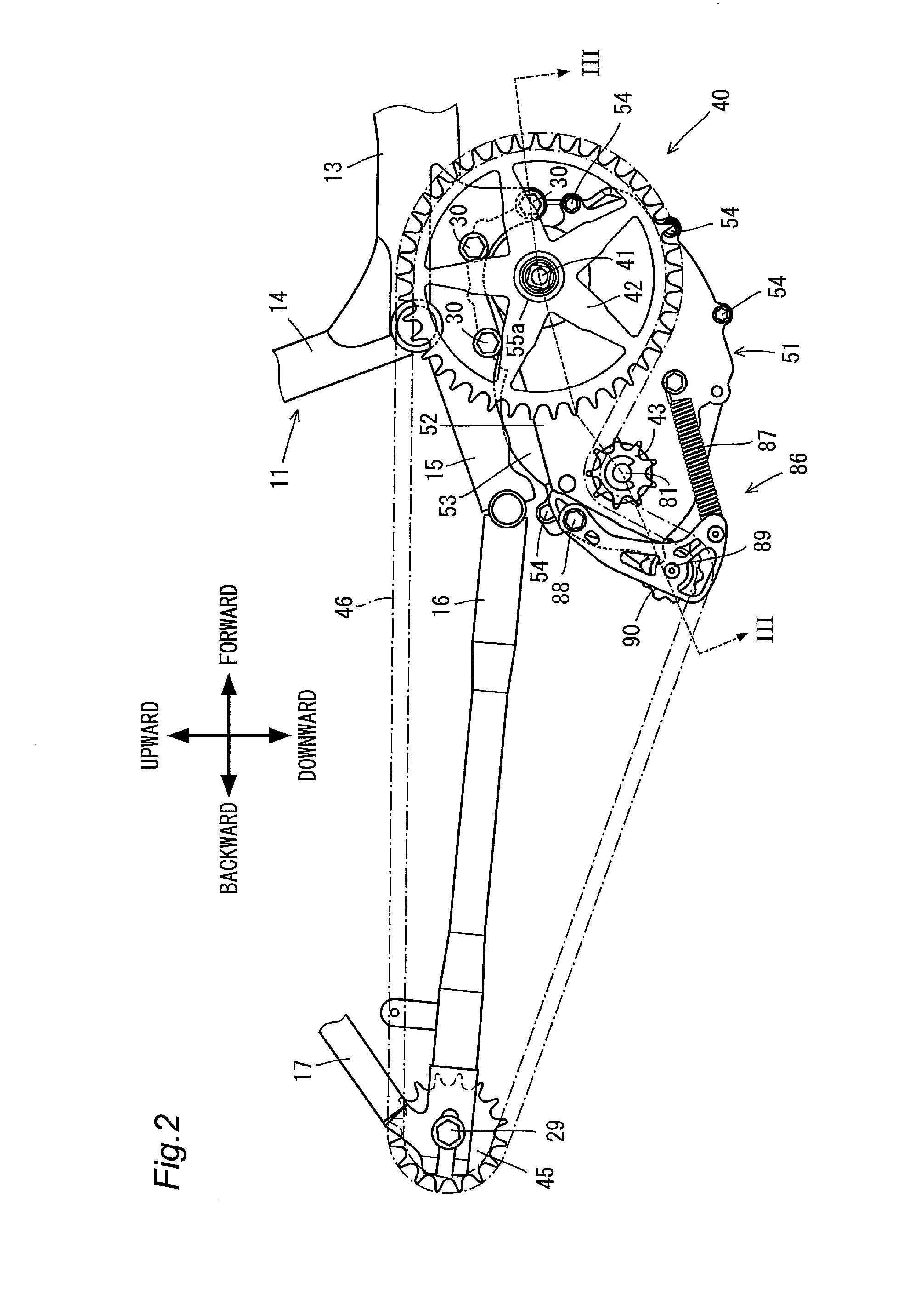
[0030]FIG. 1 shows a general structure of a battery-assisted bicycle 1 according to a first preferred embodiment of the present invention. FIG. 2 shows a general structure of a driving unit 40 and a driven sprocket 45 of the battery-assisted bicycle 1. As will be described, in this battery-assisted bicycle 1, a pedaling effort generated by a rider pushing on pedals 33 and 34 (see FIG. 1) is assisted by providing a driving force output by an electric motor 61 (see FIG. 3). More specifically, the battery-assisted bicycle 1 includes a driving mechanism that assists the pedaling effort in addition to a general structure as a bicycle.

[0031]As shown in FIG. 1, the battery-assisted bicycle 1 includes a vehicle body frame 11 that extends in a front-back direction. The battery-assisted bicycle 1 includes a front wheel 21, a rear wheel 22, the handle 23, the seat 24, and the driving unit 40.

[0032]The vehicle body frame 11 includes a head pipe 12, a down frame 13, a seat frame 14, a bracket 15...

second preferred embodiment

[0106]FIG. 8 is a flowchart for illustrating sensor failure determination for a battery-assisted bicycle according to a second preferred embodiment of the present invention. The sensor failure determination flow according to the second preferred embodiment is different from the failure determination flow according to the first preferred embodiment in that a rotation speed of the crankshaft 41 obtained from a determination result by the crank rotation detector 58 is compared to a value in a prescribed range with respect to an estimated rotation speed. In the following description, the same elements as those according to the first preferred embodiment are designated by the same reference characters and their description will not be provided while only elements different from those according to the first preferred embodiment will be described.

[0107]Steps SC1 to SC3, SC6, and SC7 in the flow in FIG. 8 are the same as steps SA1 to SA3, SA5, and SA6, respectively, in the flow in FIG. 6 ac...

third preferred embodiment

[0118]FIG. 9 shows a general structure of a sensor failure detector 120 in a battery-assisted bicycle according to a third preferred embodiment of the present invention. The structure according to the third preferred embodiment is different from the structure according to the first preferred embodiment in that its sensor failure detector 120 includes a timer 121 to count an abnormality detection duration and a detection duration determination unit 122. In the following description, the same elements as those according to the first preferred embodiment are designated by the same reference characters and their description will not be repeated while only elements different from the first preferred embodiment will be described.

[0119]As shown in FIG. 9, the sensor failure detector 120 includes the timer 121 (duration measuring unit) and the detection duration determination unit 122. The sensor failure detector 120 preferably has the same structure as that of the sensor failure detector 1...


PUM


Abstract

A battery-assisted bicycle includes a driving unit that accurately detects a failure in each of a torque detector, a crank rotation detector, and a motor rotation detector. The driving unit includes a crankshaft to which pedals are to be connected, a motor rotation detector that detects rotation of an electric motor, a torque detector that detects a torque generated at the crankshaft, a crank rotation detector that detects rotation of the crankshaft, and a sensor failure detector that detects a failure in at least one of the motor rotation detector, the torque detector, and the crank rotation detector based on detection results from the motor rotation detector, the torque detector, and the crank rotation detector.

Description

BACKGROUND OF THE INVENTION[0001]1. Field of the Invention[0002]The present invention relates to a driving unit and a battery-assisted bicycle that assists a rider's pedaling effort with a driving force from an electric motor.[0003]2. Description of the Related Art[0004]There has been a known battery-assisted bicycle that detects a torque generated at a crankshaft rotated together with pedals by a torque detector and controls an electric motor based on a detection result in order to assist the rider's pedaling effort. In such a battery-assisted bicycle, a torque generated at the crankshaft during rotation of the pedals by a rider is detected as a pedaling effort using a tension meter as disclosed in Japanese Patent No. 3412412.[0005]In such a structure adapted to detect a torque generated at the crankshaft, if the torque detector that detects a torque has a failure, appropriate assist control based on the rider's pedaling effort cannot be achieved.[0006]In contrast, there has been a...

Claims


Application Information

Patent Timeline
IPC IPC(8): B62M6/50
CPCB62M6/45B62M6/55B62M6/50B62M6/40
Inventor ARIMUNE, NOBUYASU
Owner YAMAHA MOTOR CO LTD
Learn More